Image reading apparatus

a technology of image reading and reading apparatus, which is applied in the direction of electrical apparatus, television system details, television systems, etc., can solve the problem of inability to perform image transfer to the next image processing unit, and achieve the effect of shortening the throughput time of images

Inactive Publication Date: 2013-03-19
CANON KK
View PDF4 Cites 3 Cited by
  • Summary
  • Abstract
  • Description
  • Claims
  • Application Information

AI Technical Summary

Benefits of technology

[0010]The present invention provides an image reading apparatus which can start image processing on the joint portion between the divided first and second half portions without waiting for image reading and shortens the throughput time for images by outputting each pixel on the joint portion as a start pixel to an output unit.
[0012]According to the present invention, since the photoelectric conversion element is divided into the first half portion and the second half portion in the main scanning direction, and a pixel on the joint portion between the divided first and second half portions is output as a start pixel to the output unit, it is possible to correct first the luminance difference between the right and left portions which is caused by the different characteristic between the right and left reading device portions which occurs on the joint portion. This makes it possible to start image processing at the joint portion without waiting for image reading operation, thus shortening the throughput time for images. In addition, this apparatus includes, on the right and left end portions, the shading pixel portions which receive no optical image information as reflected light from a document, and causes the transfer circuit to output data from a first pixel to the output unit upon adding data from a shading pixel portion. This makes it possible to correct the characteristic difference between the right and left reading device portions at the joint portion by comparing with images from the shading pixel portion. It is therefore possible to implement proper correction of the right and left reading levels without any influence of read images.
[0013]In addition, the document center position in the main scanning direction of an auto document feeder which automatically conveys a document to the image position of the image reading unit is made to optically almost coincide with the joint portion position between the first half portion and the second half portion in the main scanning direction of the photoelectric conversion element. This can make the numbers of read pixels on the right and left portions from the joint portion almost equal to each other in accordance with the width of a document stacked on the auto document feeder. It is therefore possible to change the number of pixels read by the photoelectric conversion element in accordance with the width of a document stacked on the auto document feeder. That is, when a document with a small width is stacked on the auto document feeder and an image is to be read from the document, since the number of read pixels in the main scanning direction can be decreased in accordance with the width of the document (the required time can be shortened), it is possible to transfer image data to the next image processing unit by reading only a necessary image without reading the entire image. This makes it possible to optimize the image read time in accordance with the document size, which is impossible to implement with a conventional CCD linear sensor required to read an entire image. It is therefore possible to improve the read throughput of documents with small sizes in the main scanning direction.

Problems solved by technology

A conventional CCD linear image sensor of a type divided into the first half portion and the second half portion, however, needs to output signals by sequentially transferring signal charges from the pixels on the right and left end portions in the main scanning direction to an output buffer because of the structural problem of the CCD in terms of the transfer of signal charges.
In this case, it is impossible to perform image transfer to the next image processing unit before the end of processing on the joint portion.

Method used


Image

  • Image reading apparatus
  • Image reading apparatus
  • Image reading apparatus

Examples


first embodiment

[0043]An example of the arrangement of the first embodiment and an example of the operation of the embodiment in a case in which the image reading apparatus of the present invention is implemented by a CCD sensor will be described below.

[0044]

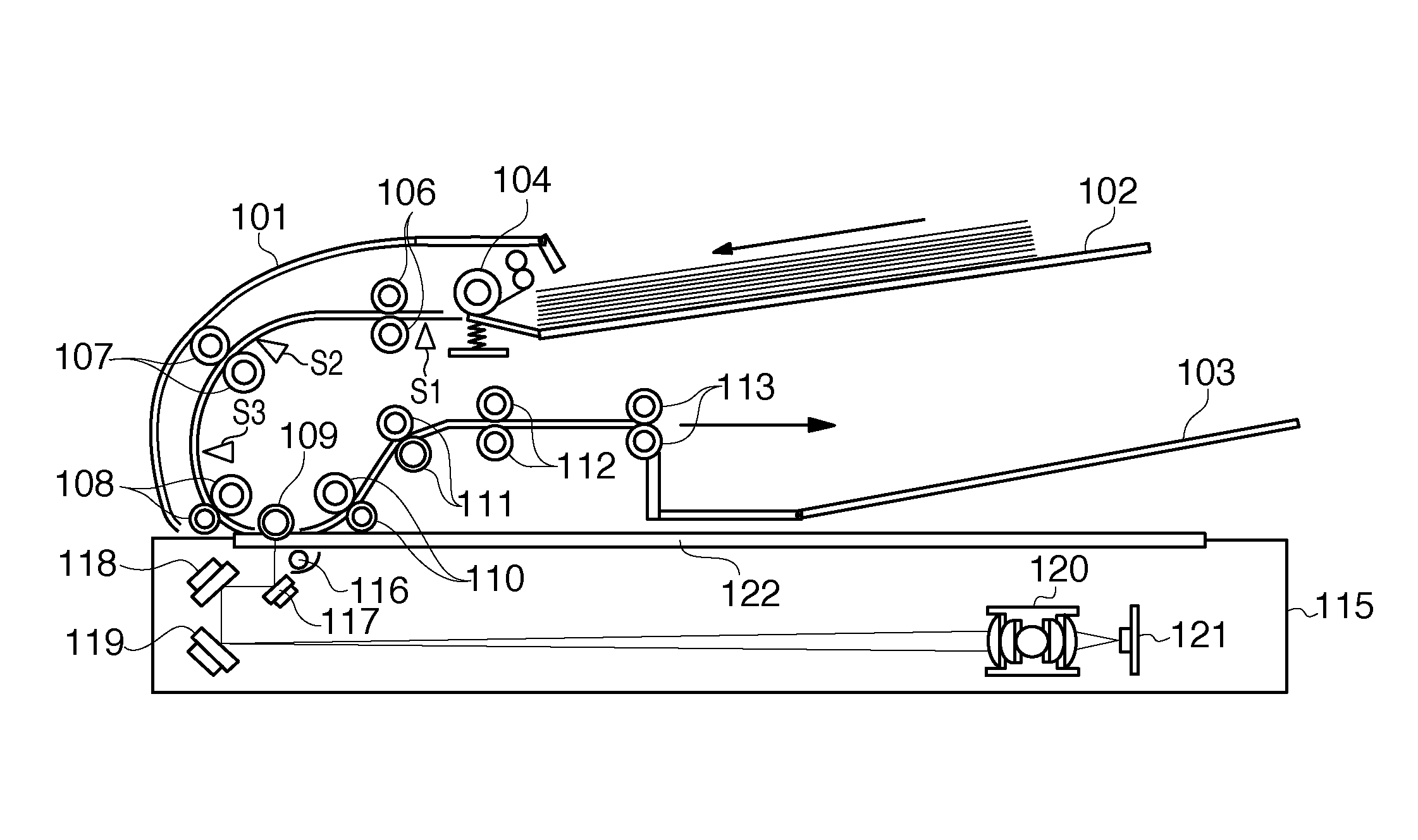
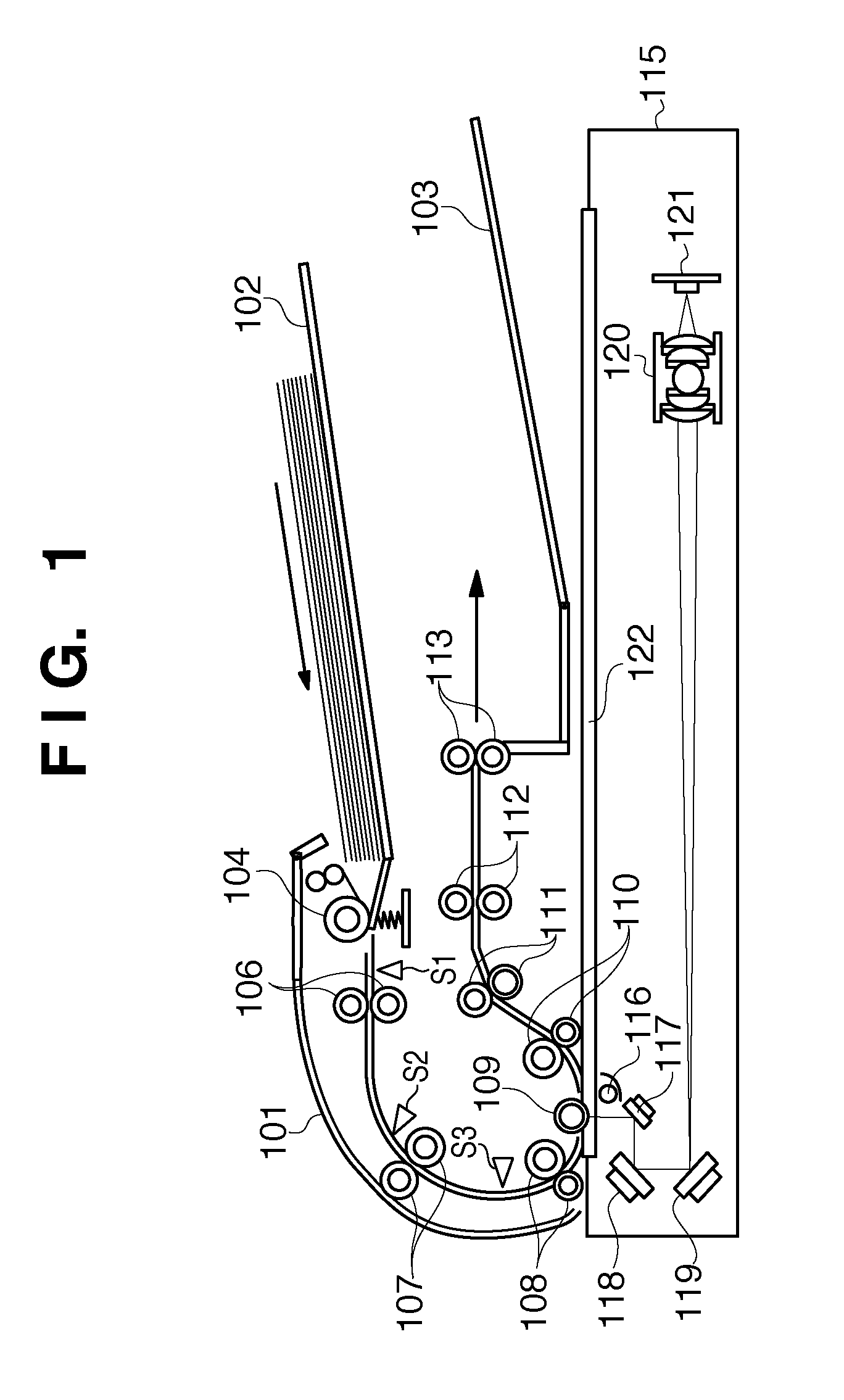
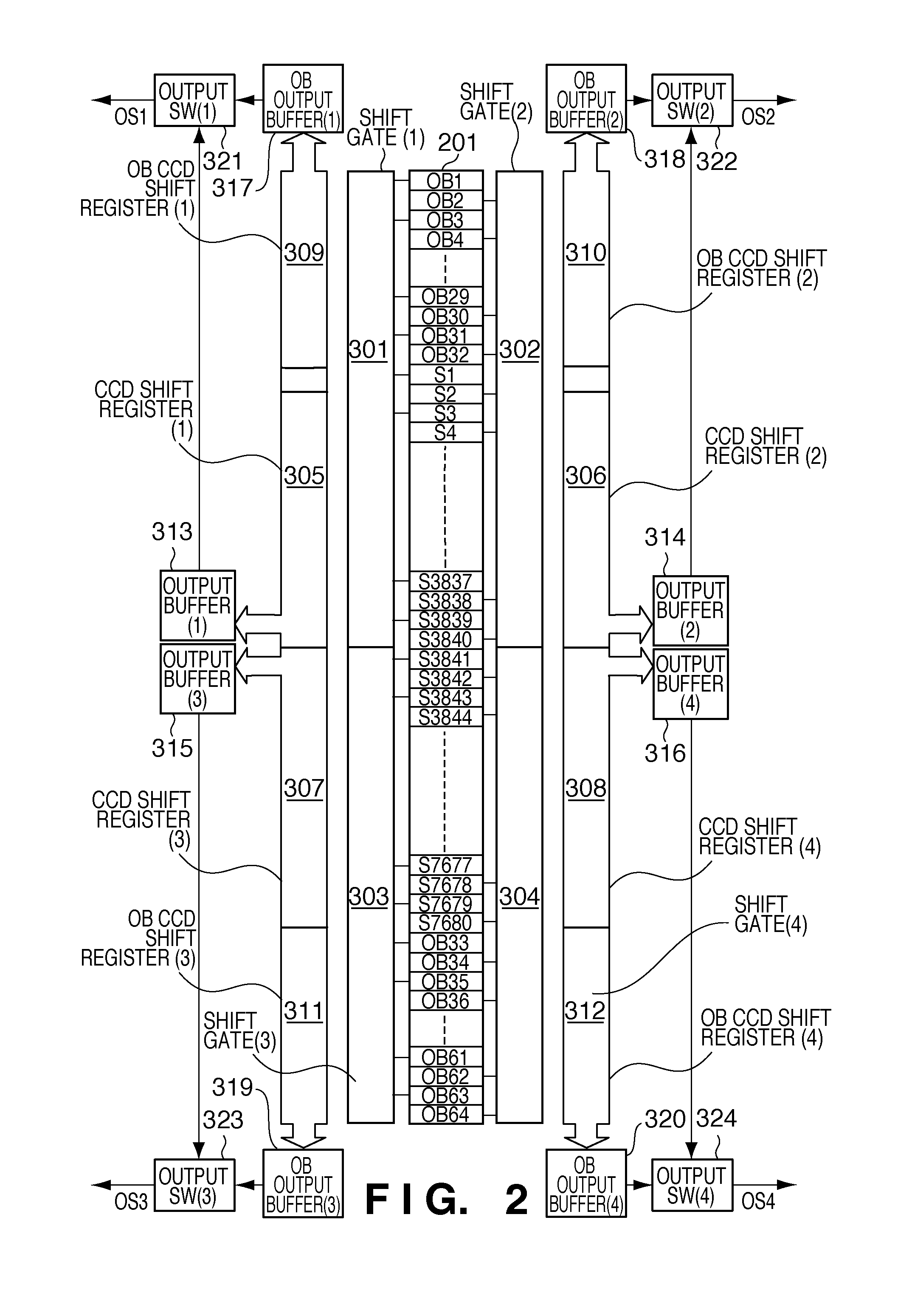
[0045]FIG. 2 shows an example of the arrangement of a CCD sensor according to this embodiment, i.e., the photoelectric conversion element 121 in FIG. 1. Reference numeral 201 denotes a photoelectric conversion element in which a plurality of CCD sensors which are pixel sensors are arranged. That is, this is a photo-detector (to be referred to as PD hereinafter) unit including PDs. PDs on which light-shielding films are formed to block light are arranged on the two end portions of the PD unit 201 so as to be arranged on each of the right and left end portions in correspondence with 32 OB pixels (OB1 to OB64) configured to detect reading levels at a dark time. These pixel portions will be referred to as shading pixel portions. PDs S1 to S7680 loc...

second embodiment

[0068]The following is an example of the arrangement of the second embodiment and an example of the operation of the embodiment in a case in which the image reading apparatus of the present invention is implemented by a CMOS sensor. To avoid a redundant description, the arrangement and operation of the second embodiment which are the same as those of the first embodiment will not be described. For such information, refer to the arrangement and operation of the first embodiment.

[0069]

[0070]FIG. 14 shows the second embodiment of the present invention, which is applied to a CMOS sensor. Like the PD unit 201 in FIG. 2, a PD unit 400 of the CMOS sensor has OB pixels provided on the two end portions, with light-receiving elements for reading an image being arranged inside the OB pixels in the main scanning direction. Output buffer+shift gates 401, 402, 403, and 404 convert charges in all the elements which is generated by the CMOS PD unit 400 into voltages, and then send the voltages to C...


PUM


Abstract

This invention provides an image reading apparatus which can start image processing on a joint portion between divided first and second half portions without waiting for image reading and shorten throughput time of image processing by outputting data from the joint portion as first data to an output unit. This apparatus includes a CCD sensor or CMOS sensor in which a plurality of pixel sensors to receive reflected light from a document are arranged in the main scanning direction and a transfer circuit configured to output, to an output unit, optical image information read at the first and second half portions of the pixel sensors in the main scanning direction. The transfer circuit outputs, to the output unit, data from the joint portion between the first and second half portions of the pixel sensors in the main scanning direction as the first data.

Description

BACKGROUND OF THE INVENTION[0001]1. Field of the Invention[0002]The present invention relates to an image reading apparatus and, more particularly, to an image reading apparatus which uses photoelectric conversion elements, as image reading elements, of a type divided into the first half portion and the second half portion in the main scanning direction.[0003]2. Description of the Related Art[0004]Conventionally, standalone image scanners and the image reading apparatuses mounted in digital copying machines and the like use CCD linear image sensors and CMOS linear image sensors. For the sake of high read rates, these image sensors use a technique called the ODD / EVEN output method which alternately allots outputs according to odd-numbered / even-numbered pixels or a method of dividing outputs into the first half portion and the second half portion in the main scanning direction (see Japanese Patent Laid-Open No. 11-261760). There has also been proposed an image sensor which can impleme...

Claims


Application Information

Patent Timeline
Patent Type & Authority Patents(United States)
IPC IPC(8): H04N1/04H04N1/46
CPCH04N1/1903H04N1/1931H04N5/361H04N5/3653H04N5/3694H04N5/37213H04N1/1013H04N1/12H04N25/672H04N25/63H04N25/7013H04N25/713
Inventor SHIRAISHI, MITSUO
Owner CANON KK
Why Eureka
Try Eureka