Laser based metal deposition of implant structures

a metal deposition and metal technology, applied in the direction of dental implants, solid-state diffusion coatings, elbow joints, etc., can solve the problems of wear or bone ingrowth characteristics, device fatigue properties that cannot be optimized for specific properties of certain portions of implants, and device bearing properties that cannot be improved, so as to improve the bearing properties of implants, improve the bone ingrowth properties of implant surfaces, and improve wear properties

Inactive Publication Date: 2005-06-09
MEDICINELODGE
View PDF11 Cites 161 Cited by
  • Summary
  • Abstract
  • Description
  • Claims
  • Application Information

AI Technical Summary

Benefits of technology

The patent describes how a process called LBMD can improve the strength and durability of dental implants. By depositing a layer of hard material on top of a porous base material, researchers have been able to create stronger and more reliable implants. Additionally, they found that even small amounts of hard materials could make significant improvements in the growth of bone cells around the implant. Overall, this technology allows for better quality implants at lower costs compared to traditional methods.

Problems solved by technology

The technical problem addressed in this patent is the need for an artificial joint that can benefit from the properties of both porous and hard materials without experiencing delamination or galvanic corrosion, while maintaining the porosity of the porous material.

Method used


Image

  • Laser based metal deposition of implant structures
  • Laser based metal deposition of implant structures
  • Laser based metal deposition of implant structures

Examples


Embodiment Construction

[0042] The following description is the best embodiment presently contemplated for carrying out this invention. This description is made for the purpose of illustrating the general principles of this invention and is not meant to limit the inventive concepts claimed herein.

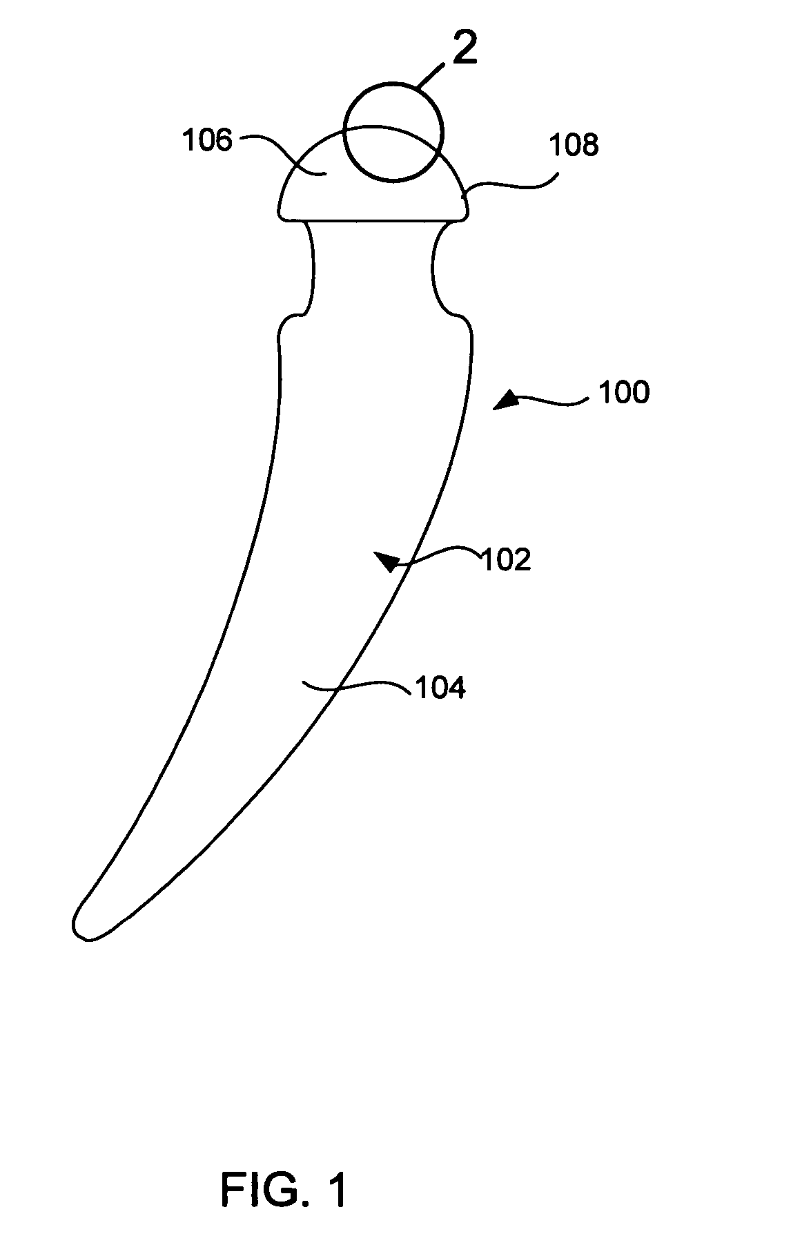
[0043] With reference to FIG. 1, a preferred embodiment of the present invention will be described in terms of a hip prosthesis (hip) 100 for implanting in the body of a patient. However, this is only by way of example, and it should be understood the present invention can practiced on many other medically implanted devices, including without limitation, knee, shoulder and elbow prostheses, as well as many other devices. Note FIG. 5, discussed below.

[0044] The hip prostheses 100 must be constructed completely of biocompatible materials in order to ensure acceptance of the prostheses by the patient's body. A biocompatible material is one that will not cause an adverse reaction with a host patient, and that will n...


PUM

PropertyMeasurementUnit
Structureaaaaaaaaaa
Corrosion propertiesaaaaaaaaaa
Hardnessaaaaaaaaaa

Abstract

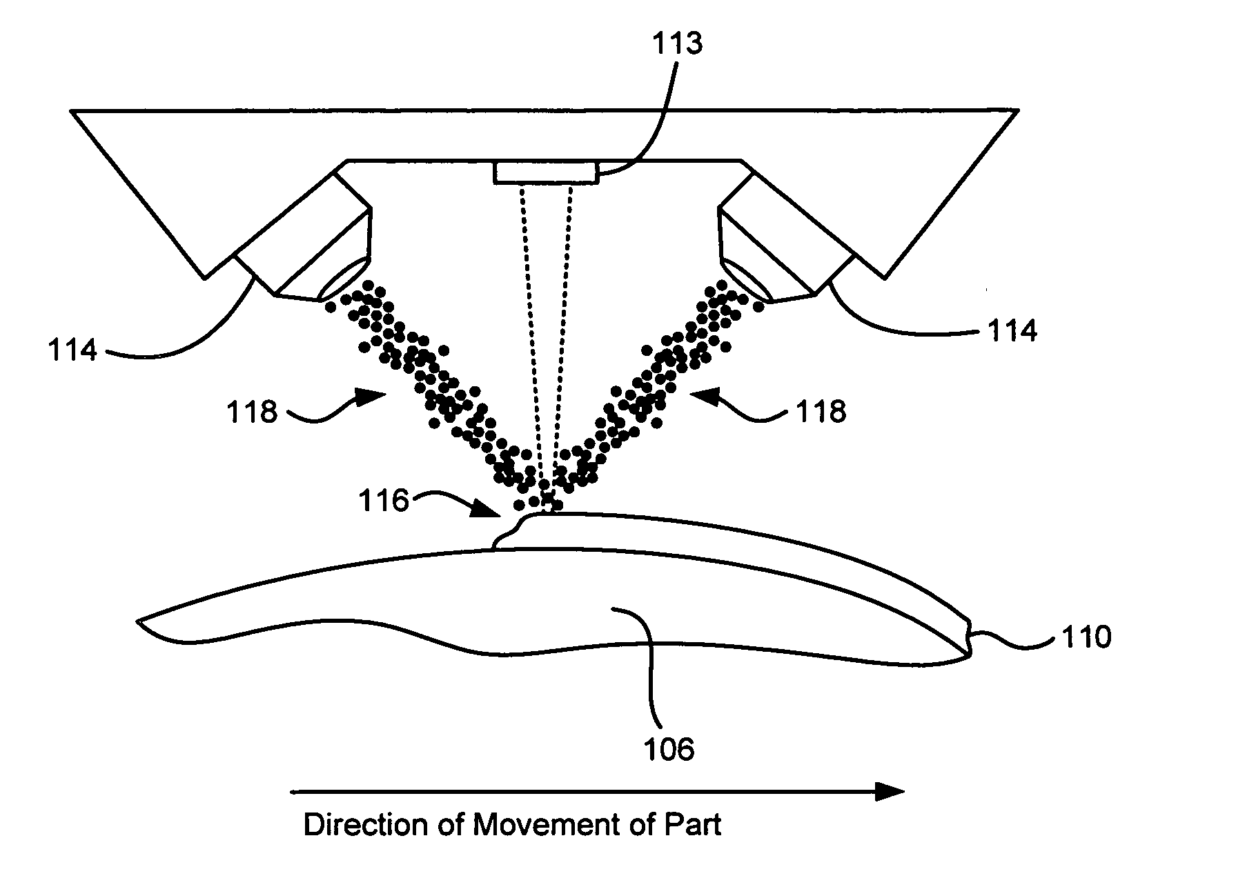
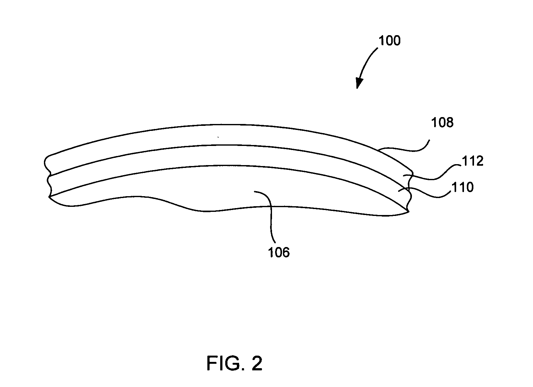
A method of depositing a hard wear resistant surface onto a porous or non-porous base material of a medical implant. The medical implant device formed by a Laser Based Metal Deposition (LBMD) method. The porous material of the base promotes bone ingrowth allowing the implant to fuse strongly with the bone of a host patient. The hard wear resistant surface provides device longevity when applied to bearing surfaces such as artificial joint bearing surface or a dental implant bearing surface.

Description


Claims


Application Information

Patent Timeline
Owner MEDICINELODGE
Why Eureka
Try Eureka