
Method for producing a sliding element

a technology of sliding element and sliding bearing, which is applied in the field of method for producing sliding element, can solve the problems of only recycling with considerable effort, high cost of monometallic sliding bearing composed of such materials, and punching offcuts, and achieve the effect of improving the sliding properties of the bearing and reducing the weight of the sliding elemen

Pending Publication Date: 2022-02-03
WIELAND WERKE AG
View PDF10 Cites 0 Cited by
  • Summary
  • Abstract
  • Description
  • Claims
  • Application Information

AI Technical Summary

Benefits of technology

The invention is a method for producing a sliding element with lubricating pockets that are economical and efficient. The method involves using a composite material with a thin layer of copper or aluminum alloy on a steel back. The composite material can be produced by laser roll cladding, which involves connecting two band-shaped or strip-shaped materials in a way that creates a solid metallic composite. The resulting sliding element has excellent sliding properties and can be used in high-load applications. The invention provides an efficient and cost-effective solution for producing sliding elements with lubricating pockets.

Problems solved by technology

On account of the high metal price of copper, monometallic sliding bearings composed of such materials are expensive.
However, the resultant punching offcuts are not of one type and can therefore be recycled only with considerable effort.

Method used


Image

  • Method for producing a sliding element
  • Method for producing a sliding element
  • Method for producing a sliding element

Examples


Embodiment Construction

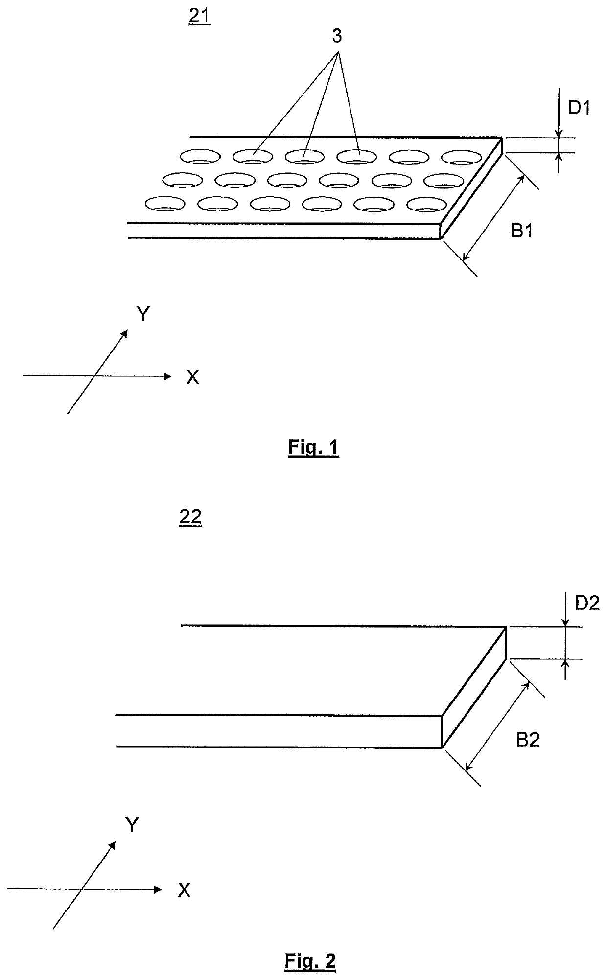
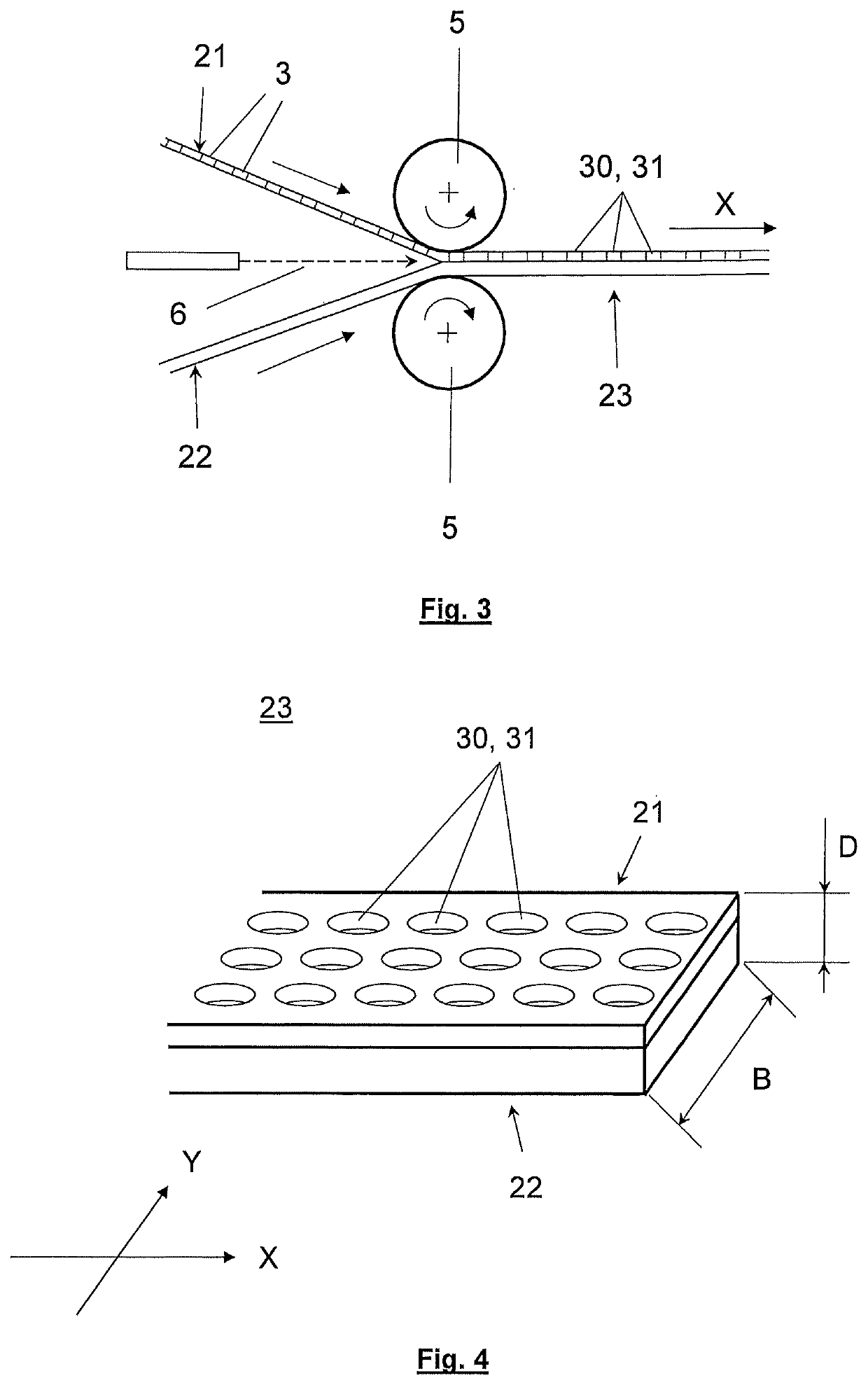
[0040]FIG. 1 shows a first material 21 in the form of a band material of width B1 and of thickness D1. The band-shaped material extends over an undefined length in the X direction. The width B1 is measured in the Y direction. The thickness D1 is measured in a direction that is perpendicular to X and Y. The material has a multiplicity of apertures 3. The apertures 3 may have a round shape as in the illustrated case. Other shapes, such as for example oval, elongate, triangular or rectangular, are also possible.

[0041]FIG. 2 shows a second material 22 in the form of a band material of width B2 and of thickness D2. The band-shaped material extends over an undefined length in the X direction. The width B2 is measured in the Y direction. The thickness D2 is measured in a direction that is perpendicular to X and Y. In the illustrated case, the second material 22 is embodied as a solid material and has planar surfaces. Neither apertures nor any other structural elements are present.

[0042]FIG...


PUM

PropertyMeasurementUnit
angleaaaaaaaaaa
thicknessaaaaaaaaaa
areaaaaaaaaaaa

Abstract

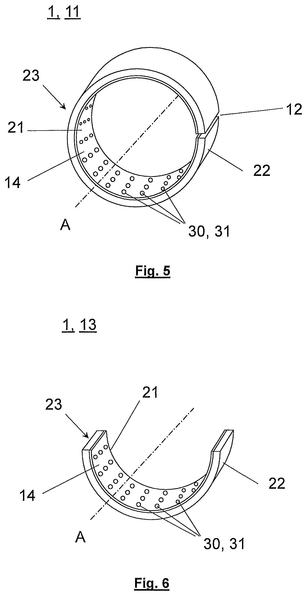
A method for producing a sliding element, providing a first band-shaped or strip-shaped metallic material of a thickness, wherein the first material has apertures which extend over the entire thickness of the first material, providing a second band-shaped or strip-shaped metallic material of a thickness, areally connecting the first band-shaped or strip-shaped material to the second band-shaped or strip-shaped material by laser roll cladding such that a band-shaped or strip-shaped composite material is formed, which has a longitudinal direction X and a transverse direction, and has a thickness oriented perpendicularly with respect to the longitudinal and transverse directions. The method further includes bending the composite material about an axis oriented parallel to the transverse direction of the composite material, such that a sliding element is formed which has cutouts on its running surface that are formed at least partially from the apertures of the first material.

Description

CROSS-REFERENCE TO RELATED APPLICATION[0001]This claims priority from German Application No. 10 2020 004 652.5, filed Jul. 31, 2020, the disclosure of which is hereby incorporated by reference in its entirety.TECHNICAL FIELD[0002]The invention relates to a method for producing a sliding element having lubricating pockets.BACKGROUND AND SUMMARY[0003]Sliding elements having lubricating pockets on the running surface are used in applications with particularly high loads on the bearing surfaces. The lubricating pockets may be formed as recesses in the running surface or as apertures which extend over the entire thickness of the sliding element. Perforated bushings are an example of such sliding elements.[0004]Certain copper alloys have excellent sliding properties and are therefore suitable as a material for the running surface of sliding bearings. On account of the high metal price of copper, monometallic sliding bearings composed of such materials are expensive. Therefore, use is ofte...

Claims


Application Information

Patent Timeline
Patent Type & Authority Applications(United States)
IPC IPC(8): F16C33/14F16C33/10F16C33/12
CPCF16C33/14F16C2220/44F16C33/125F16C33/1095F16C33/10B21D53/10B23K20/04B23K20/008
Inventor THUMM, GERHARDVOGGESER, VOLKER
Owner WIELAND WERKE AG
Learn More