Method for optimizing a grooved bearing pattern on a bearing surface of a fluid dynamic bearing for the purpose of improving the bearing properties and an appropriate grooved bearing pattern

a technology of fluid dynamic bearings and grooved bearings, which is applied in the direction of bearing components, shafts and bearings, bearings, etc., can solve the problems of affecting the bearing performance, so as to prevent the occurrence of negative pressure zones and improve the bearing properties.

Inactive Publication Date: 2009-06-25
MINEBEA CO LTD
View PDF17 Cites 11 Cited by
  • Summary
  • Abstract
  • Description
  • Claims
  • Application Information

AI Technical Summary

Benefits of technology

[0005]Based on the above-mentioned problems, it is the object of the invention to provide a method for optimizing a grooved bearing pattern on a bearing surface of a fluid dynamic bearing for the purpose of improving the bearing properties and also to provide an appropriate grooved pattern, where, in particular, the occurrence of negative pressure zones should be prevented.

Problems solved by technology

On operation of the bearing, these bearing patterns generate a pumping effect on the bearing fluid and thus a build up of pressure in the bearing gap.
Should negative pressure zones arise or the overall bearing pressure be too low, damage to the bearing or its failure could result.
Due to cavitation effects, negative pressure zones are built up in the bearing in which air bubbles can escape from the bearing fluid and form air cushions that impair the function of the bearing and, in the worst case, result in a failure of the bearing.
The present geometry of the ends of the grooved bearing patterns, which substantially always have the same width and depth, is not suited for the prevention of such negative pressure zones, particularly at high rotational speeds of the bearing.

Method used


Image

  • Method for optimizing a grooved bearing pattern on a bearing surface of a fluid dynamic bearing for the purpose of improving the bearing properties and an appropriate grooved bearing pattern
  • Method for optimizing a grooved bearing pattern on a bearing surface of a fluid dynamic bearing for the purpose of improving the bearing properties and an appropriate grooved bearing pattern
  • Method for optimizing a grooved bearing pattern on a bearing surface of a fluid dynamic bearing for the purpose of improving the bearing properties and an appropriate grooved bearing pattern

Examples


Embodiment Construction

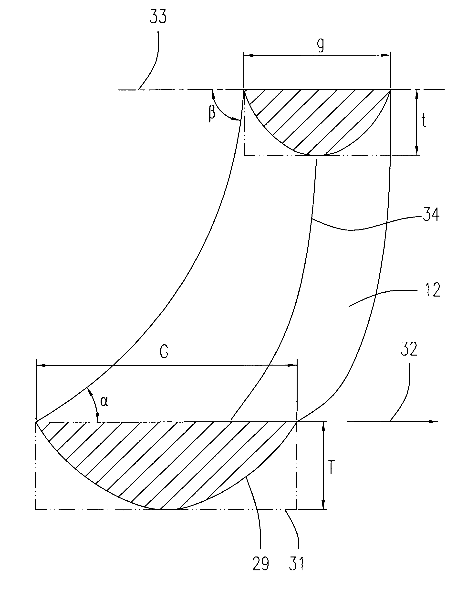
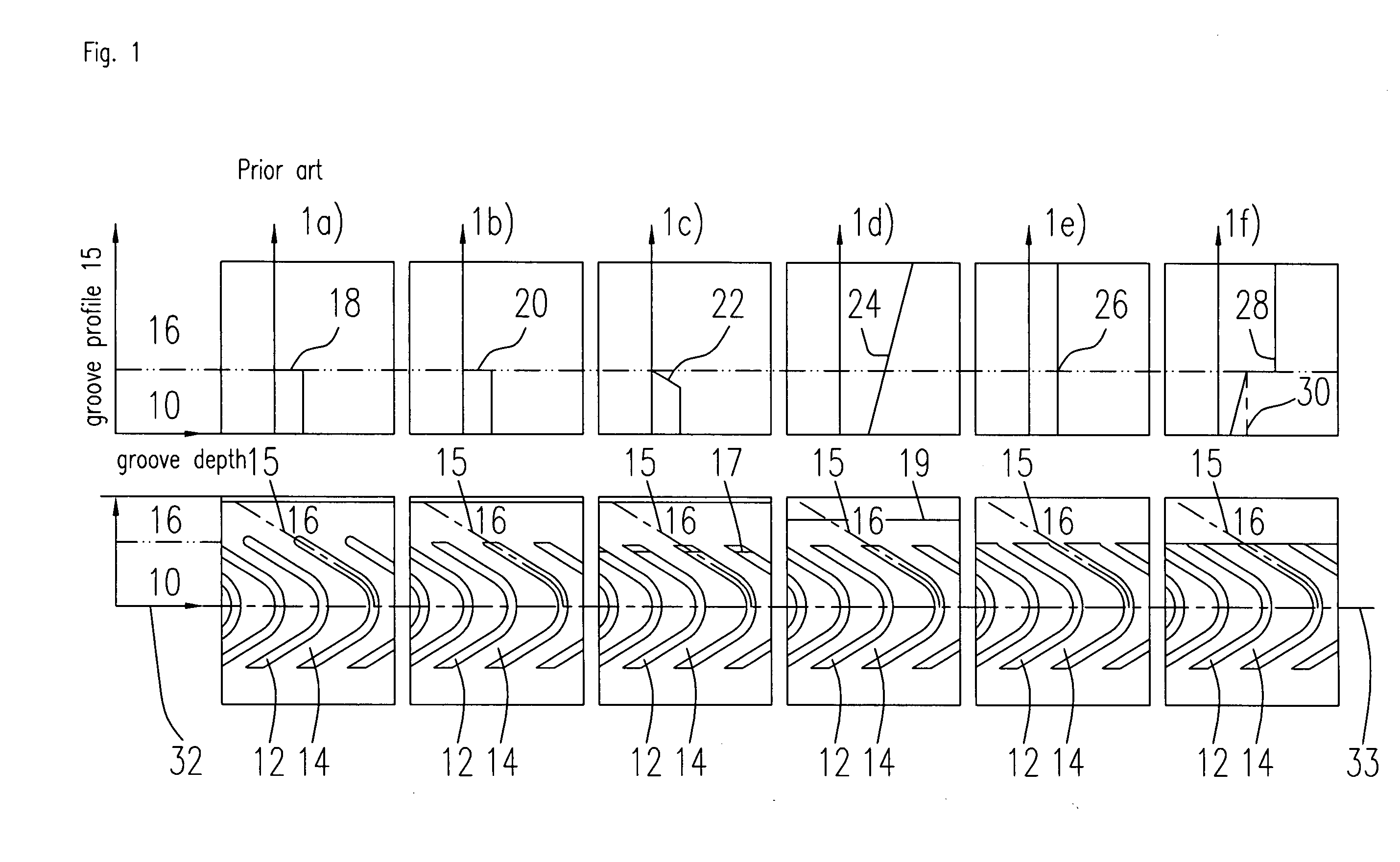
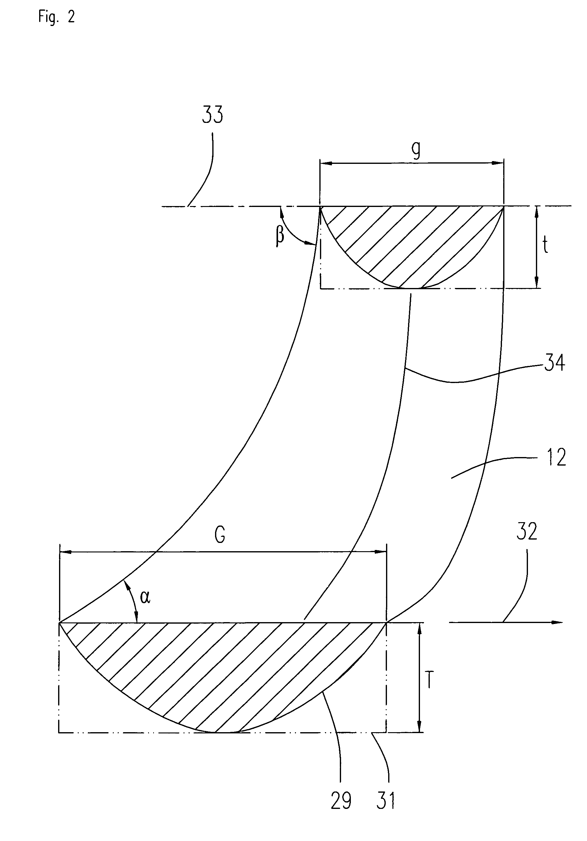
[0038]The present invention also proposes, in particular, to change, variably or incrementally, the depth, width and the angle of the grooved bearing patterns over their length in order to control the pumping effect on the bearing fluid generated by the grooved bearing patterns and the pressure generated in the bearing gap. FIG. 1 shows several variants 1a to 1f of grooved bearing patterns for a radial bearing that, in the example, are formed as sine-shaped grooved bearing patterns that are disposed within a bearing zone 10. The bearing zone 10, which comprises the grooved bearing patterns 12, is bounded by a rim zone 16. In the lower section of the respective drawings 1a to 1f, a view from above of the bearing surface having grooved bearing patterns is shown, whereas in the upper section, a depth profile of the grooved bearing patterns along the measuring line 15 is shown.

[0039]FIG. 1a depicts the prior art. FIG. 1a shows grooved bearing patterns 12 that are formed in a bearing sur...


PUM


Abstract

The invention relates to a method for optimizing a grooved bearing pattern on a bearing surface of a fluid dynamic bearing for the purpose of improving the bearing properties as well as an appropriately designed grooved bearing pattern, the grooved bearing pattern having a defined length, width and depth, and the bearing surface being moveable with respect to another associated bearing surface in at least one direction of movement, having the following steps:
selection of a bearing property to be improved, optimization of the geometry of the grooved bearing pattern in respect of the bearing property to be improved by adjusting one or more of the following parameters of the grooved bearing pattern:
depth, width, length, angle with respect to direction of movement of the bearing surface or its normal, contour, geometry of the transition to adjacent surfaces.

Description

TECHNICAL FIELD OF THE INVENTION[0001]The invention relates to a method for optimizing a grooved bearing pattern on a bearing surface of a fluid dynamic bearing for the purpose of improving the bearing properties of this bearing. An appropriate grooved bearing pattern for realizing the method is also described.PRIOR ART[0002]Grooved bearing patterns of the type described above find application, for example, in fluid dynamic bearings, as used, for example, for the rotatable support of spindle motors. A fluid dynamic bearing comprises at least two preferably rotatable bearing parts moveable with respect to each other that are separated from one another by a bearing gap filled with bearing fluid. The bearing is given its load-carrying capacity by a fluid dynamic effect that, on operation of the bearing, causes a build up of pressure in the bearing fluid and thus in the bearing gap. This fluid dynamic effect is generated by bearing patterns that are provided on one or both of the bearin...

Claims


Application Information

Patent Timeline
Patent Type & Authority Applications(United States)
IPC IPC(8): F16C32/06
CPCF16C33/10
Inventor JIANG, LEIBAUER, MARTIN
Owner MINEBEA CO LTD
Why Eureka
Try Eureka