
Optimized push-to-talk call setup

Inactive Publication Date: 2005-06-09
KYOCERA CORP
View PDF3 Cites 42 Cited by
  • Summary
  • Abstract
  • Description
  • Claims
  • Application Information

AI Technical Summary

Benefits of technology

[0009] The considerable time required by conventional systems to establish a push-to-talk call is a significant problem in the field of wireless communications. Some conventional systems may be able to achieve times as low as 2.5 seconds to establish a PTT call. The present invention provides improved methods for establishing a PTT call that significantly reduce the conventional setup time.
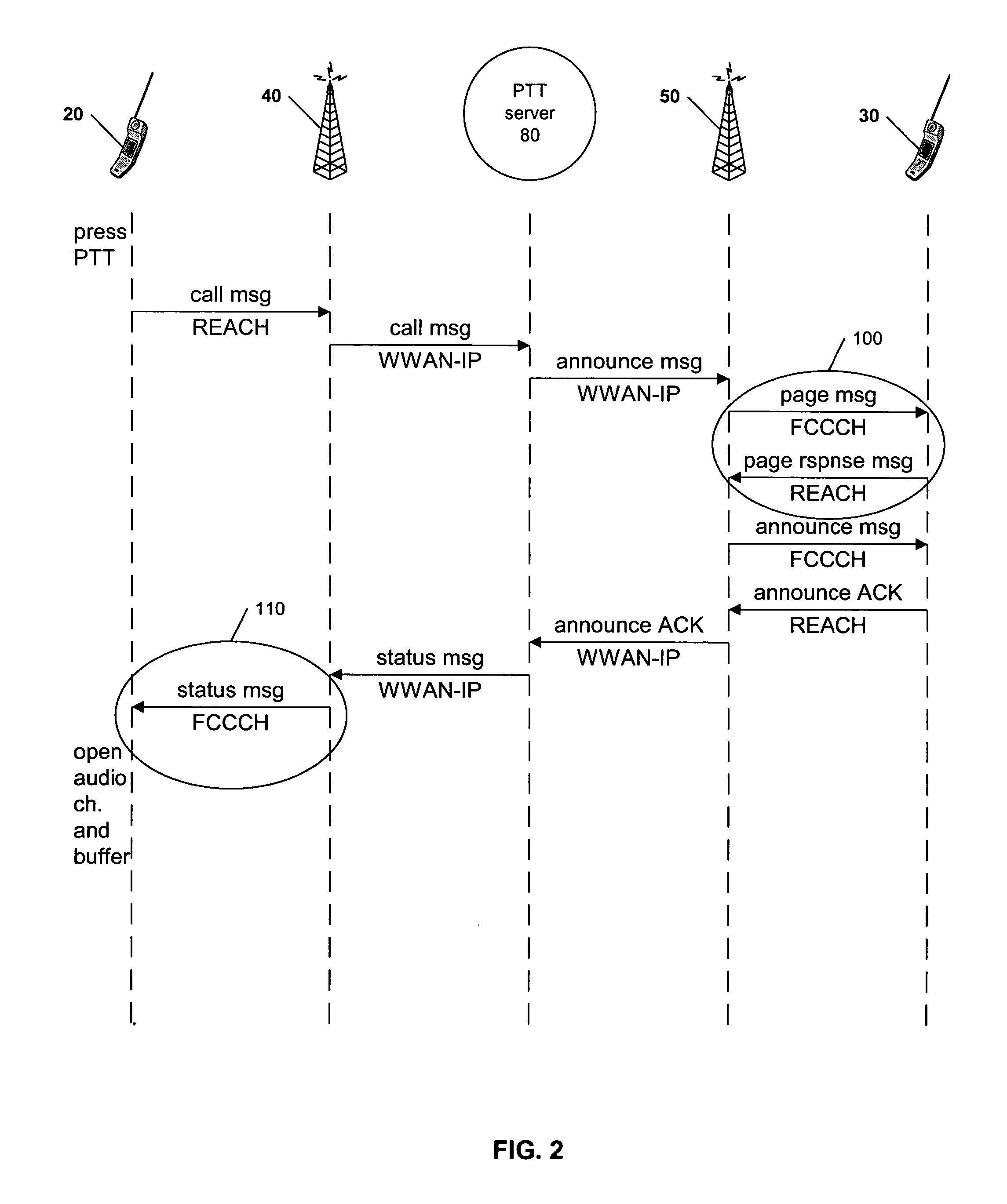
[0010] When the connection status message is sent by the PTT server to the requesting handset, the delay in delivering that message is eliminated by sending the message to the requesting handset in a control channel. Thus, delivery of the connection status message is not dependant upon establishing a traffic channel. Accordingly, the requesting handset may indicate to the caller (i.e., the user of the requesting handset) that the connection has been made and the caller may begin speaking. The handset turns on the audio channel and buffers the caller's voice until the traffic channel is established. At that time, the caller's buffered voice signals are sent to the target handset.

Problems solved by technology

Conventional systems and methods for establishing a push-to-talk (“PTT”) call over a wireless communication network suffer from significant call setup times. Typically, a call message from a requesting handset is received by a PTT server that subsequently sends out an announce message to the target handset.
A significant drawback of these conventional methods for establishing a PTT call is the amount of time required to locate the target handset.
However, the connection status message is delayed at the base station until the wireless communication network has established a traffic channel for the PTT call.
This delay in delivering the connection status message significantly increases the PTT call setup time.
The considerable time required by conventional systems to establish a push-to-talk call is a significant problem in the field of wireless communications.

Method used


Image

  • Optimized push-to-talk call setup
  • Optimized push-to-talk call setup
  • Optimized push-to-talk call setup

Examples


Embodiment Construction

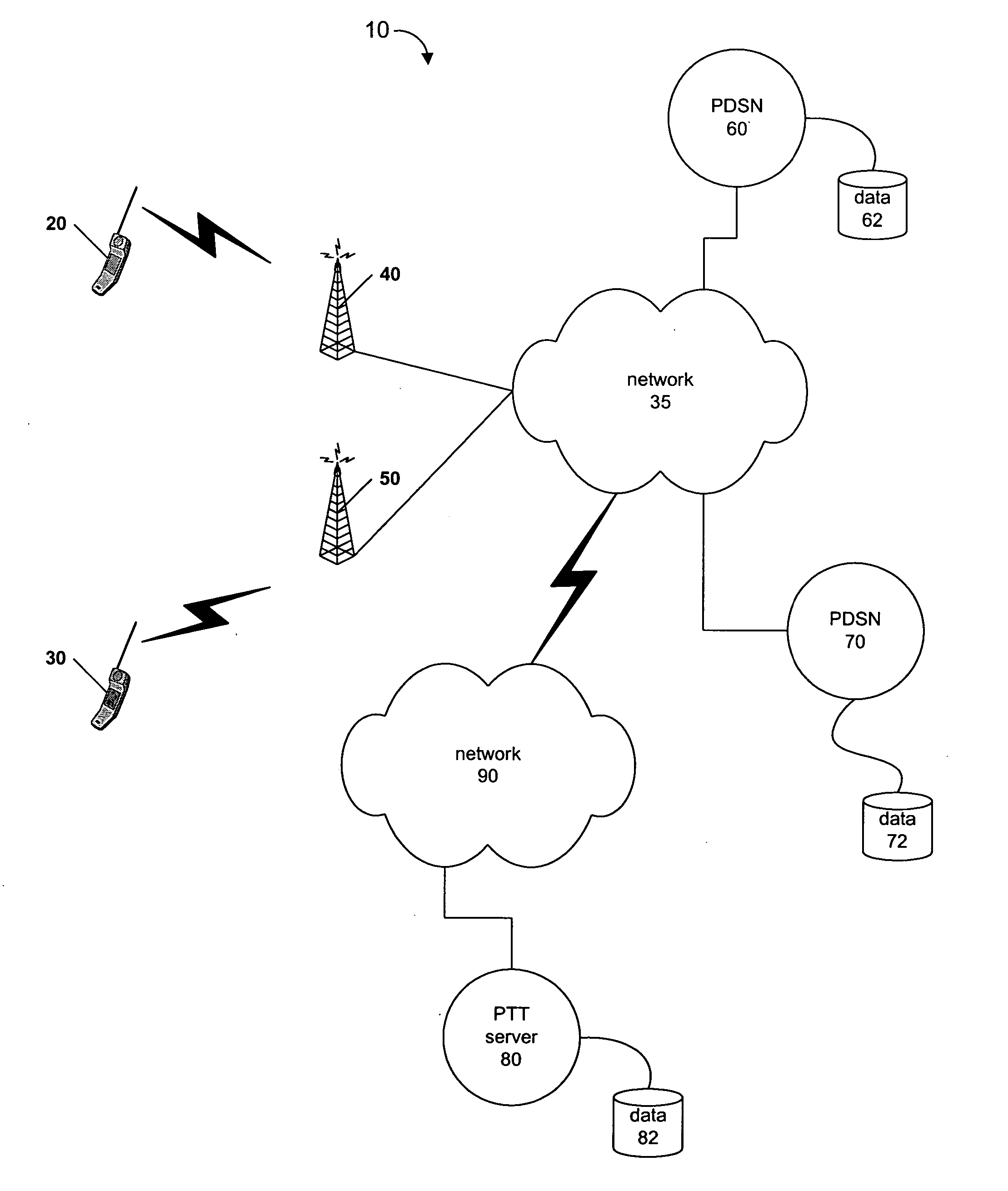
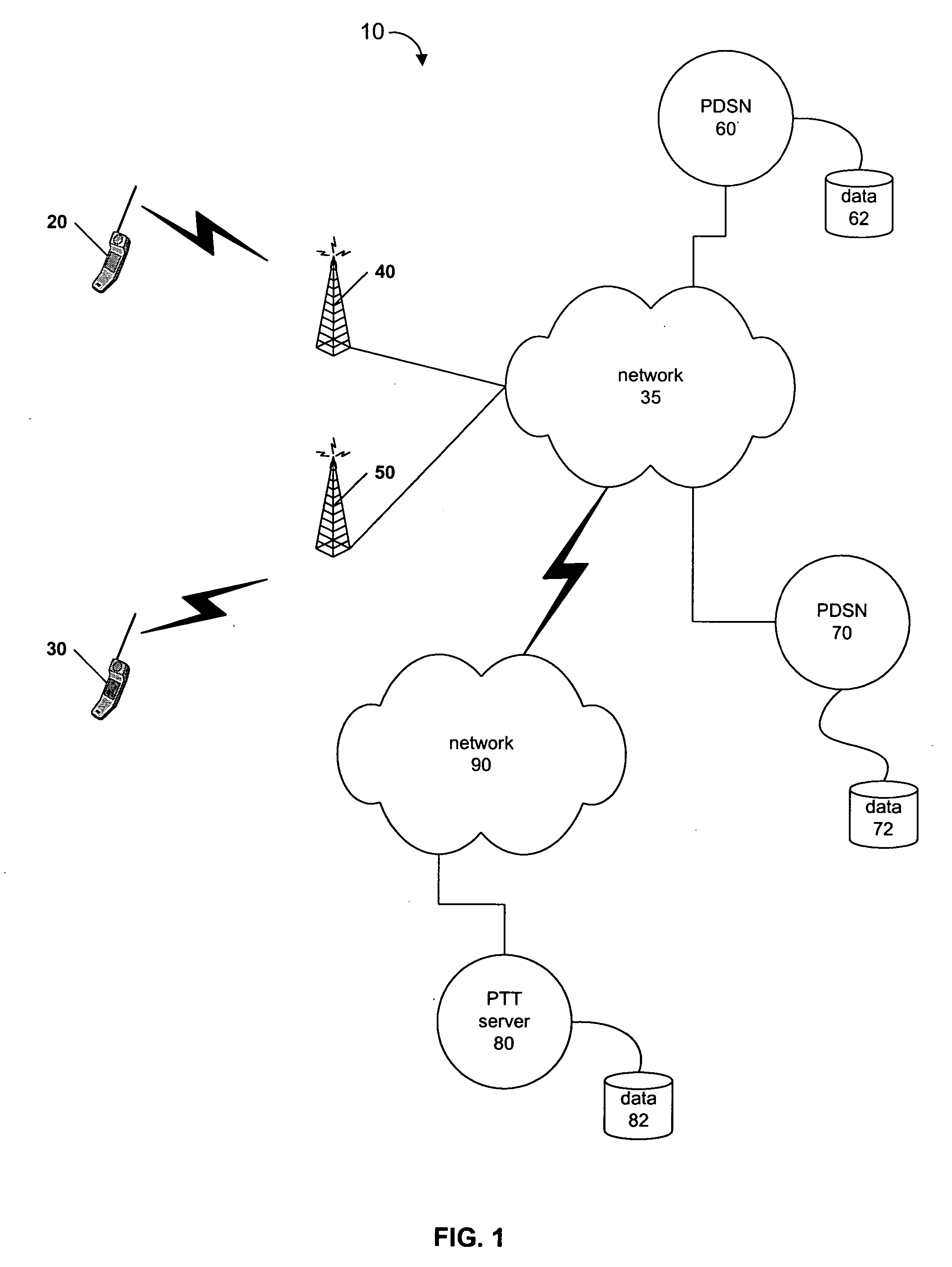
[0020] Disclosed herein are systems and methods for optimizing push-to-talk call setup over a wireless communication network. For example, one method as disclosed herein allows for a requesting handset to send a call request message to establish a PTT call with a target handset. In response to the call request message, the requesting handset receives a connection status message in a control channel. The requesting handset then turns on the audio channel and buffers any received audio until a traffic channel for the PTT call has been established.

[0021] After reading this description it will become apparent to one skilled in the art how to implement the invention in various alternative embodiments and alternative applications. However, although various embodiments of the present invention will be described herein, it is understood that these embodiments are presented by way of example only, and not limitation. As such, this detailed description of various alternative embodiments shou...


PUM


Abstract

A requesting handset in a wireless communication network sends a call message requesting a push-to-talk connection with a target handset. In response, a push-to-talk server sends a connection status message to the requesting handset. The connection status message is sent to the requesting handset in a control channel such as the forward common control channel. The requesting handset indicates to the caller that the connection has been made with the target handset, turns on the audio channel, and buffers any audio received from the caller until the traffic channel has been established. Once the traffic channel is established, any buffered audio is sent over the traffic channel and the push-to-talk call ensues.

Description

RELATED APPLICATION [0001] The present application relates to co-pending U.S. patent application Ser. No. ______ entitled DIRECTED FLOOD OF PUSH-TO-TALK ANNOUNCE MESSAGE, of concurrent ownership, filed concurrently herewith, which is incorporated herein by reference in its entirety.BACKGROUND [0002] 1. Field of the Invention [0003] The present invention generally relates to wireless communications and more specifically relates to establishing push-to-talk communication between wireless communication devices. [0004] 2. Related Art [0005] Conventional systems and methods for establishing a push-to-talk (“PTT”) call over a wireless communication network suffer from significant call setup times. Typically, a call message from a requesting handset is received by a PTT server that subsequently sends out an announce message to the target handset. In order to send the announce message to the target handset, however, the target handset must first be located. Accordingly, conventional systems...

Claims


Application Information

Patent Timeline
IPC IPC(8): H04W4/10H04W72/04
CPCH04W4/10H04W76/005H04L65/1016H04L65/4061H04W76/02H04W76/45H04W76/10
Inventor HASSAN, TARIQ A.SADAGOPAN, VIJAYKRISHNA
Owner KYOCERA CORP
Learn More