Controller for work implement of construction machinery, method for controlling construction machinery, and program allowing computer to execute this method

a technology for construction machinery and control devices, which is applied in the direction of electric programme control, program control, instruments, etc., can solve the problems of operator operating a lever of operation swinging with the operability spoiled, operation delayed with the work efficiency lowered, and enabling smooth and quick operation of the work implement. , to achieve the effect of eliminating the delay time in starting or stopping the operation, ensuring the suppression of vibrations, and enabling the effect of smooth and quick operation

Inactive Publication Date: 2005-08-11
KOMATSU LTD
View PDF7 Cites 46 Cited by
  • Summary
  • Abstract
  • Description
  • Claims
  • Application Information

AI Technical Summary

Benefits of technology

[0022] A main object of the present invention is to provide a controller for a work implement, a method for controlling the work implement, and a program for making computer execute this method, which enabling more smooth and quick operations of the work impl...

Problems solved by technology

For instance, a construction machine such as a hydraulic shovel carries out various types of works by driving a work implement consisting of an arm or a boom, there is the problem that vibrations occur in the work implement when an operation of the work implement is stopped or the work implement is started from the rest state.
In a case where the work implement is driven by an actuator including a hydraulic cylinder, this phenomenon occurs when supply of a hydraulic oil to the actuator is transitionally stopped or supply of a hydraulic oil is started suddenly all at once, and also because an inertial force of the operation machine in the rest state or in the operating state can not smoothly be absorbed.
When vibrations occur in a work implement with large inertia such as a boom or an arm, the entire hydraulic shovel largely swing, so that also an operator operating an operation lever thereof swing with the operability spoiled.
Further, when the work implement is swinging, it is impossible to shift an operation of the work implement to the next one, so that the operation is delayed with the work efficiency lowered.
It is possible to suppress vibrations of the work implement in the rest state or upon start of the operations thereof by making the work implement run slowly, but in this state, the performance of the hydraulic shovel is not fully achieved, and the work efficiency is low also in this state.
Because of this feature, the speed change in the work implement ...

Method used


Image

  • Controller for work implement of construction machinery, method for controlling construction machinery, and program allowing computer to execute this method
  • Controller for work implement of construction machinery, method for controlling construction machinery, and program allowing computer to execute this method
  • Controller for work implement of construction machinery, method for controlling construction machinery, and program allowing computer to execute this method

Examples


first embodiment

1. First Embodiment

(1) General Configuration

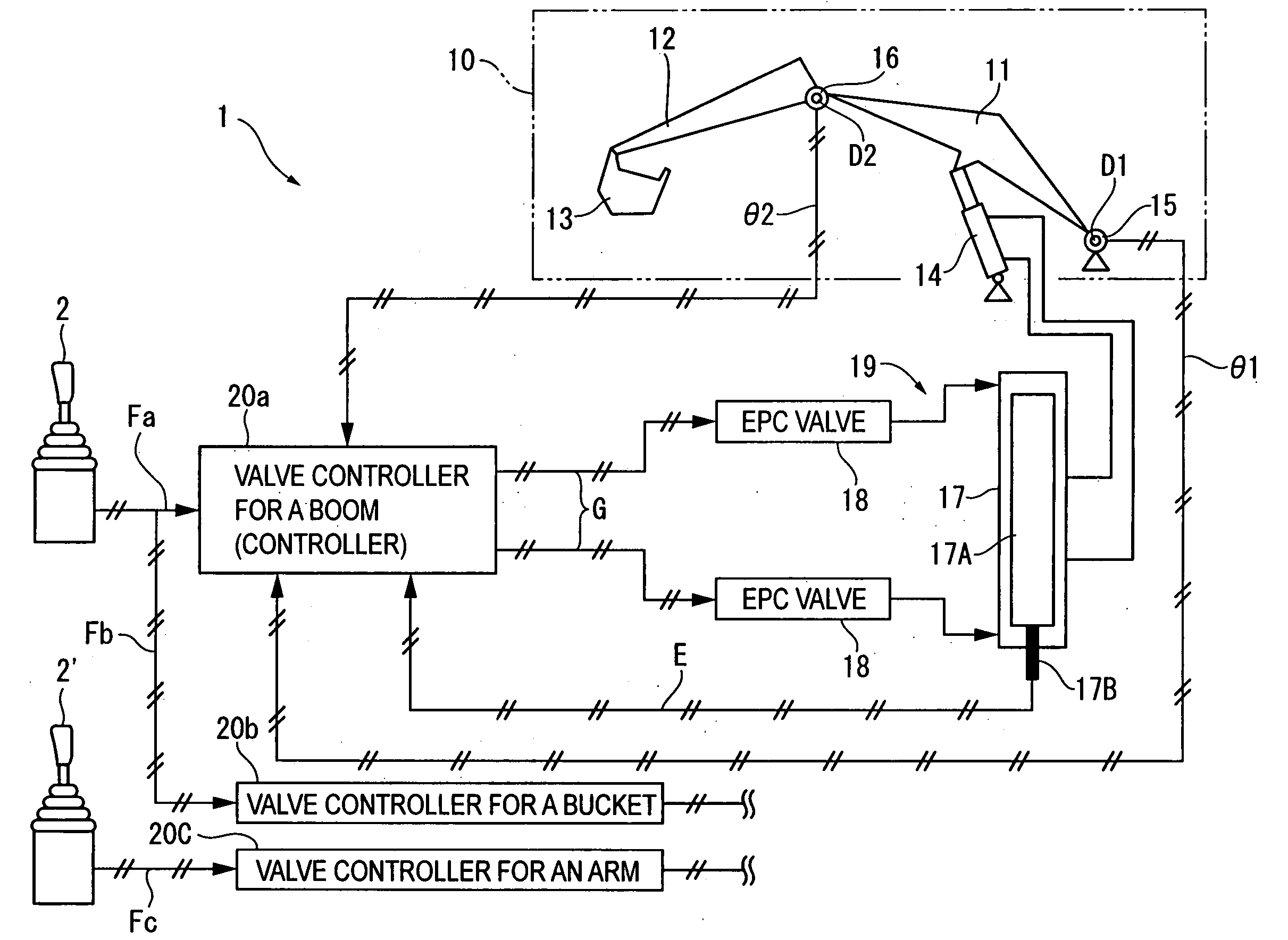
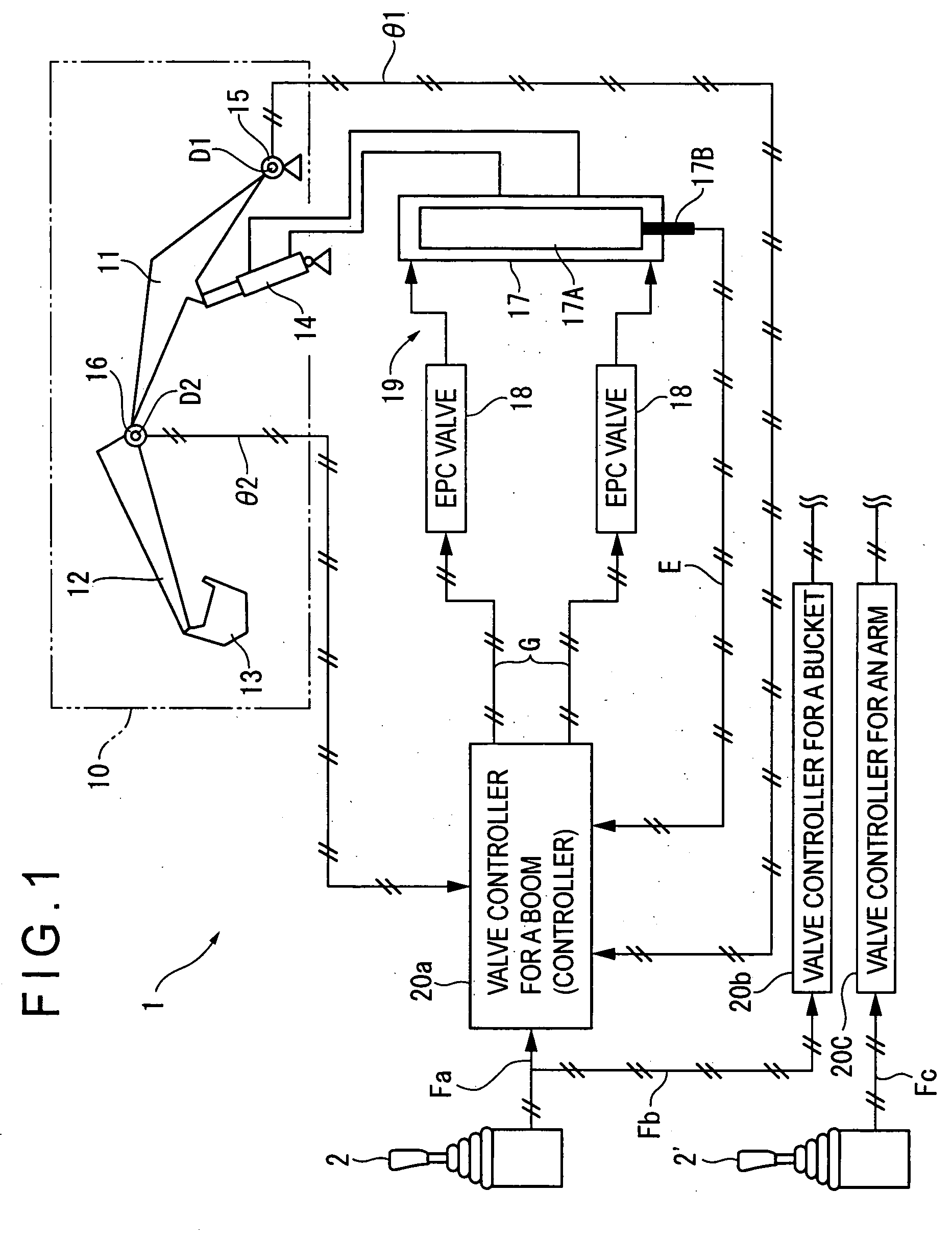
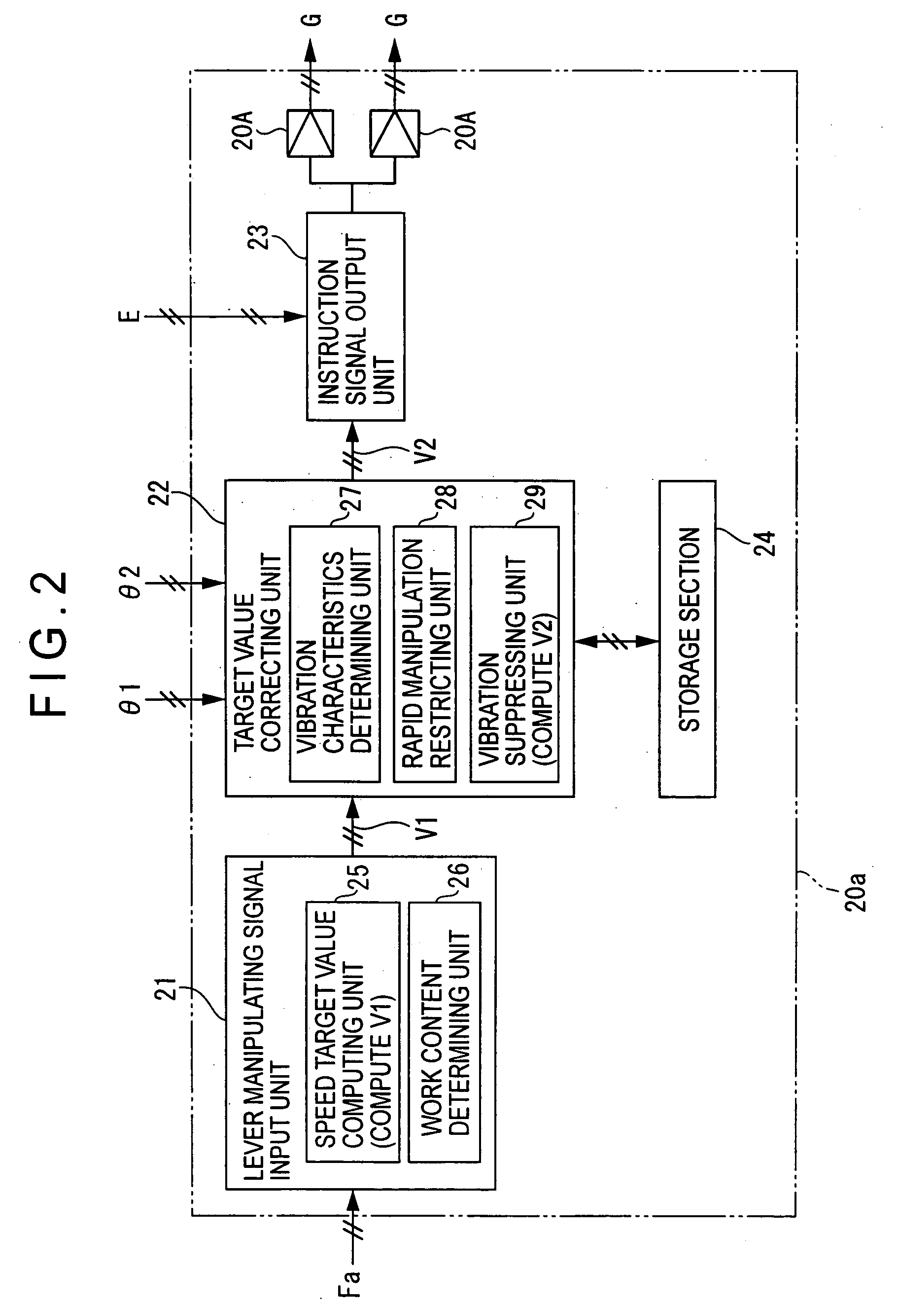
[0050]FIG. 1 is a schematic view showing a hydraulic shovel (construction machine) 1 with a work implement and a controller for the same according to one embodiment of the present invention mounted thereon. FIG. 2 is a block diagram showing the controller.

[0051] In FIG. 1, the hydraulic shovel 1 comprises a boom 11 manipulated by a lever 2, and an arm 12 manipulated by a lever 2′, and a bucket 13 is attached to a tip of the arm 12.

[0052] The boom 11 is rotated around a supporting point D1 by a hydraulic cylinder 14.

[0053] The arm 12 is rotated around a supporting point D2 by a hydraulic cylinder on the boom 11. The bucket 13 is rotated by a hydraulic cylinder on the arm 12 when the lever 2 is manipulated in the other direction. A work implement 10 according to the present invention is formed with the boom 11, arm 12, and bucket 13.

[0054] In this embodiment, details of the present invention are described with reference to the boom 11 ...

second embodiment

2. Second Embodiment

[0147] A second embodiment of the present invention is described below. In the following descriptions, the same reference numerals are used for the same components and functions already described and description thereof is omitted herefrom or simplified herein.

[0148] The first embodiment described above is a case where the present invention is applied to the hydraulic shovel 1, and in this case, the joint angles θ1 and θ2 of the boom 11 and arm 12 are detected, the characteristic frequency ω and damping coefficient ξ, are computed from the detected joint angles θ1 and θ2, and correction of the speed target value V2 is carried out based on the computed characteristic frequency ω and damping coefficient ξ.

[0149] In contrast, in the second embodiment, the present invention is applied to a wheel loader 3 as shown in FIG. 10, and this embodiment is different from the first embodiment described above in the point that an joint angle θ of a boom 31 constituting a work...

third embodiment

3. Third Embodiment

[0172] A third embodiment of the present invention is described below.

[0173] The joint angle θ of the boom 31 and the hydraulic oil pressure P by the hydraulic cylinder 33 are inputted as signals to the controller 30a according to the second embodiment described above, and the vibration characteristics determining unit 38 in the target value correcting unit 37 determines the characteristic frequency ω and damping coefficient ξ based on the joint angle θ and the hydraulic oil pressure P.

[0174] The third embodiment is different from the embodiments described above in that, as shown in FIG. 14, a force sensor 41 such as a distortion gauge is provided near the bucket 32 at a tip of the boom 31 constituting the work implement 30 of the wheel loader 3, and a pay load due to the earth and sand SD or the like in the bucket 32 is detected as a distortion signal W for the boom 31 by the force sensor 41, and the distortion signal is outputted to a controller 40a. In the co...


PUM


Abstract

A controller for a work implement (10, 30) of a construction machine (1, 3) comprising: a manipulating signal input unit (21) including a target value computing section (25) for generating an operation target value (V1) for the work implement (10, 30) based on a manipulating signal (F, Fa) inputted from a manipulating unit (2) for manipulating the work implement (10, 30), a target value correcting unit (22, 37) for correcting the generated operation target value (V1), and an instruction signal output unit (23) for outputting an instruction signal to an actuator (19, 34) for driving the work implement (10, 30) according to the corrected target value (V2); wherein the target value correcting unit (22, 37) comprises a vibration suppressing unit (29) for correcting the operation target value (V1) to another target value to suppress vibrations of the construction machine (1, 3) according to the vibration characteristics, which vary according to a posture of and/or a load to the work implement (10, 30).

Description

BACKGROUND OF THE INVENTION [0001] 1. Field of the Invention [0002] The present invention relates to a controller for work implement of construction machinery, a method for controlling a construction machinery, and a program allowing a computer to execute this method. [0003] 2. Description of Related Art [0004] For instance, a construction machine such as a hydraulic shovel carries out various types of works by driving a work implement consisting of an arm or a boom, there is the problem that vibrations occur in the work implement when an operation of the work implement is stopped or the work implement is started from the rest state. [0005] In a case where the work implement is driven by an actuator including a hydraulic cylinder, this phenomenon occurs when supply of a hydraulic oil to the actuator is transitionally stopped or supply of a hydraulic oil is started suddenly all at once, and also because an inertial force of the operation machine in the rest state or in the operating ...

Claims


Application Information

Patent Timeline
IPC IPC(8): E02F3/43E02F9/22E02F9/20G05B13/00G05B19/00
CPCE02F9/2207F16L1/24F16L9/12
Inventor OKAMURA, KENJINOSE, MATSUOKIMURA, YOICHIRO
Owner KOMATSU LTD
Why Eureka
Try Eureka