Vehicle access system

a technology of vehicle access and vehicle, applied in the field of vehicle access system, can solve the problems of adversely affecting the conventional narrow band scheme, rf environment, etc., and achieve the effect of increasing the time interval between repeating the polling signal and conserving power

Active Publication Date: 2017-02-07
JAGUAR LAND ROVER LTD
View PDF29 Cites 52 Cited by
  • Summary
  • Abstract
  • Description
  • Claims
  • Application Information

AI Technical Summary

Benefits of technology

[0010]The use of an ultra-wideband transmitter for transmitting the polling signal is advantageous in that the power required to generate the polling signal is very low. Because of the low power demand, it is possible for the polling signal to be used to initiate communication between the access unit and the further access unit. In this way, it is not necessary for there to be an initial trigger, such as the user operating the door handle. Rather, communication can be initiated wirelessly. Thus, any delay experienced by the user in opening the vehicle door can be eliminated without the need to incur the additional cost of a fast-release motor in the door. Furthermore, because the polling signal is transmitted over such a wide bandwidth, it is resistant to multi-path fading which adversely affects conventional narrow band schemes in ‘crowded’ RF environments. This enables the use of the polling signal to reliably initiate communication between the access unit and the further access unit in situations where there are lots of reflections.
[0014]At least the first transmitter may be configured: to increase the time interval between transmissions of the polling signal in response to an increase in the distance between the access unit and the further access unit; and / or to reduce the time interval between transmissions of the polling signal in response to a reduction in the distance between the access unit and the further access unit.
[0015]At least the first transmitter may be configured to modify the length of the time interval between transmissions of the polling signal in dependence on the distance between access unit and the further access unit, wherein said distance is determined based on the time of flight of communications between the access unit and the further access unit. It is a particular advantage of ultra-wide communications that it is possible to distinguish between signals which travel along a direct path between transmitter and receiver and those which follow non-direct paths. Accordingly, this allows the distance between the access unit and the further access unit to be established with a high degree of accuracy, much more so than distance measurements in conventional narrow-band systems which typically rely on radio signal strength intensity (RSSI) measurements.
[0042]The polling signal could be continuous. However, to conserve power, the polling signal can be pulsed with a time interval between transmissions. The time interval between transmissions of the polling signal can be greater than or equal to: 0.5 seconds, 1 second, 2 seconds, 3 seconds, 5 seconds or 10 seconds. An increased time interval can help to conserve power.
[0078]According to yet another aspect of the present invention there is provided a first access unit for communicating with a second access unit to control access to a vehicle, the first access unit being portable and comprising: at least a first transmitter for transmitting a polling signal; and at least a first receiver for receiving an authentication signal from the second access unit; wherein the first access unit is configured to disable at least the first receiver and / or at least the first transmitter if the first access unit remains substantially stationary for a predetermined period of time. The first access unit can be an electronic key, for example in the form of a key fob. By selectively deactivating at least the first receiver and / or at least the first transmitter, unnecessary dialogue between the first and second access units can be avoided to preserve the battery.

Problems solved by technology

Furthermore, because the polling signal is transmitted over such a wide bandwidth, it is resistant to multi-path fading which adversely affects conventional narrow band schemes in ‘crowded’ RF environments.

Method used


Image

  • Vehicle access system
  • Vehicle access system
  • Vehicle access system

Examples


Embodiment Construction

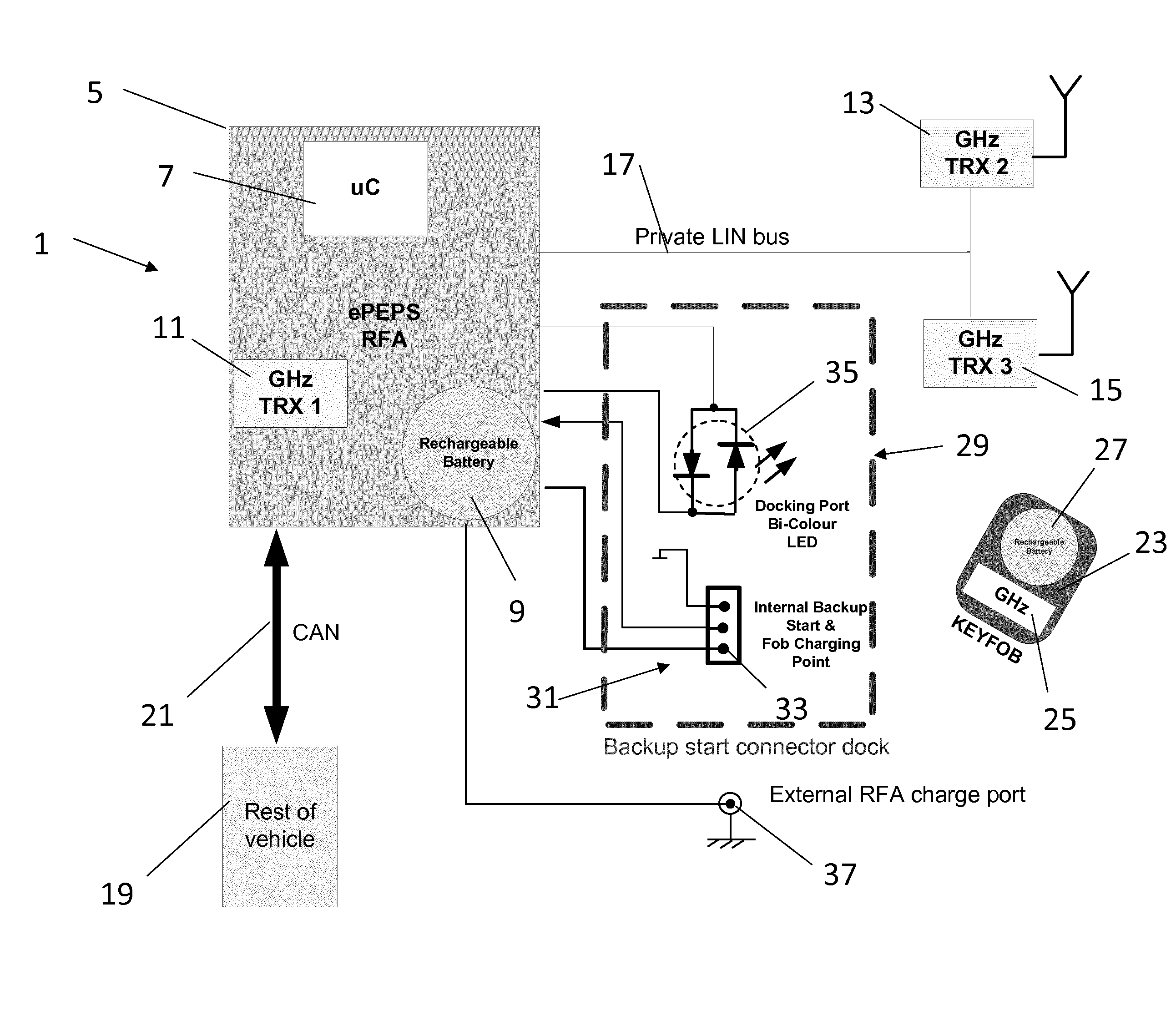
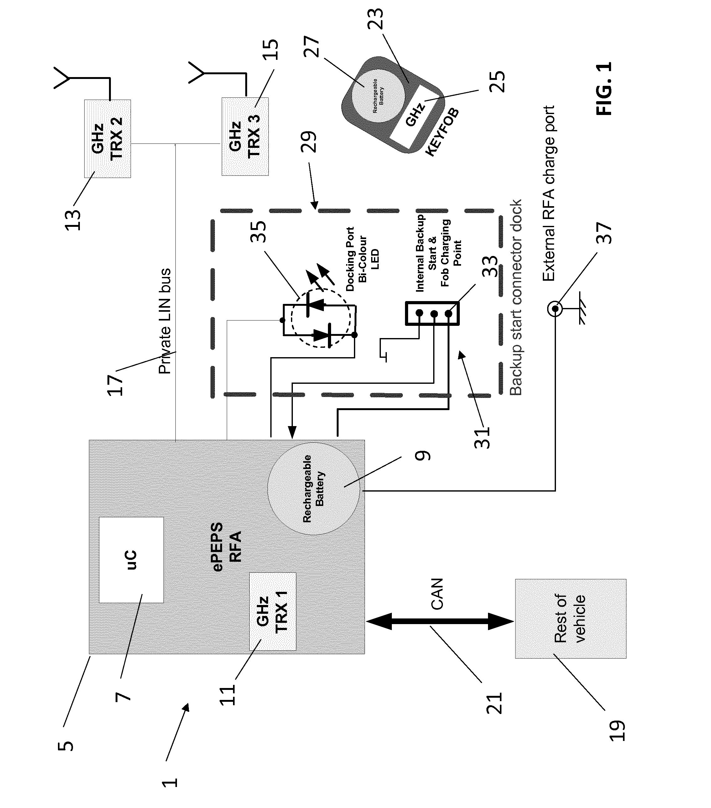
[0090]An access system 1 in accordance with an embodiment of the present invention is shown in FIG. 1. The vehicle access system 1 is configured to provide enhanced Passive Entry and Passive Start (ePEPS) of a vehicle 3. In particular, the vehicle access system 1 supports keyless access and, optionally, remote engine start.

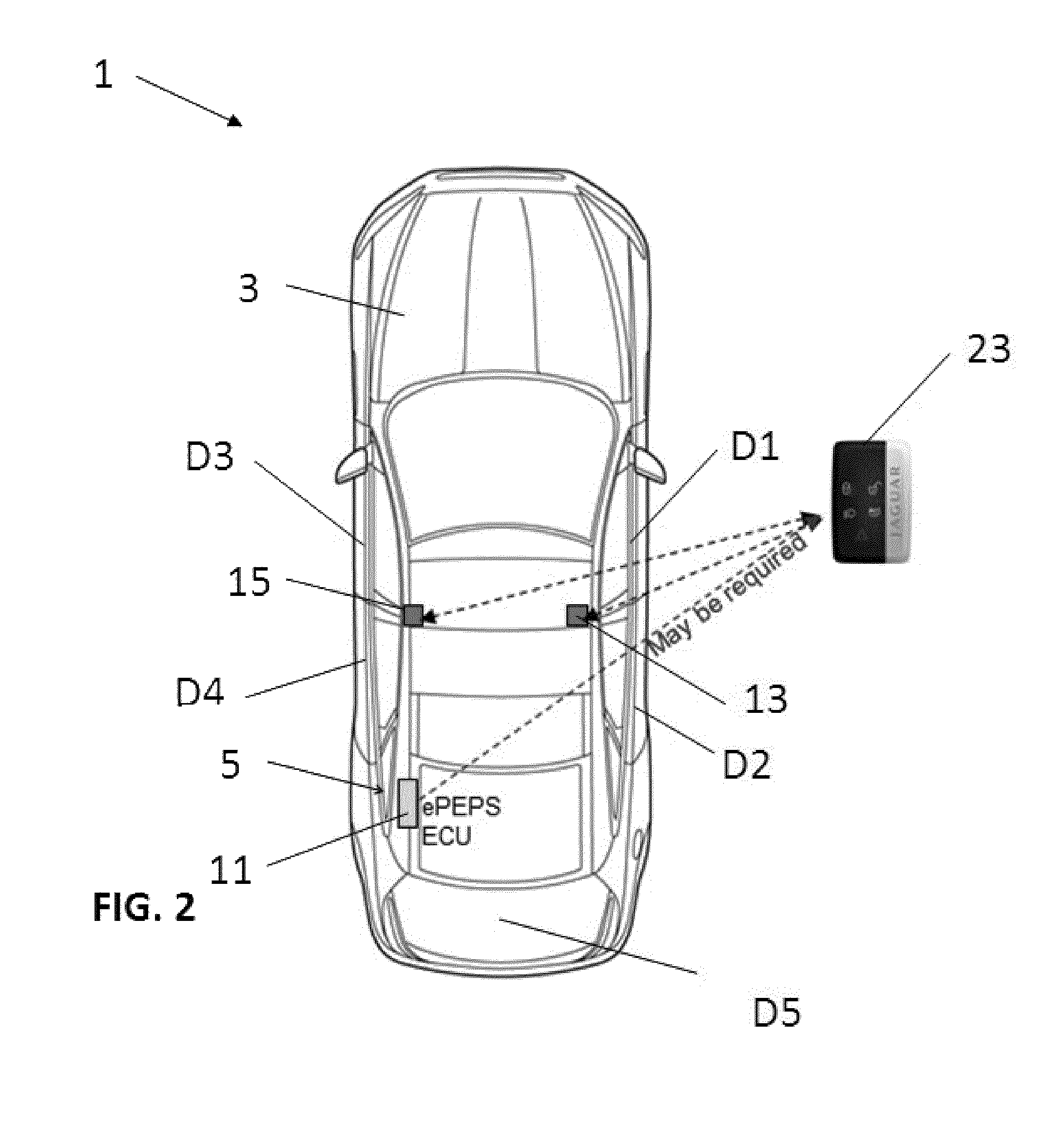
[0091]The vehicle access system 1 will be described with reference to the vehicle 3 which has a front right door D1, a rear right door D2, a front left door D3 and a rear left door D4. The vehicle 3 also has a boot lid D5 (also known as a deck lid) which can be locked / unlocked by the vehicle access system 1 but this is not described herein for the sake of brevity. The doors D1-D4 each have a lock mechanism and an external handle; and the front doors D1, D3 each have a folding door mirror. The lock mechanisms each comprise a door lock switch to provide a locking signal to indicate the status of the respective lock mechanism.

[0092]The vehicle access system 1 compris...


PUM


Abstract

The invention relates to an access unit (5; 23) for communicating with a further access unit (5; 23) to control access to a vehicle (3). The access unit (5; 23) comprises at least a first transmitter (11; 25) for transmitting a polling signal; and at least a first receiver (11; 25) for receiving an authentication signal from the further access unit (5; 23) in response to the polling signal. At least the first transmitter (11; 25) is a first ultra-wideband transmitter and at least the first receiver (11; 25) is a first ultra-wide-band receiver. The invention also relates to a vehicle access system (1) which is a combination of the access and further access units (5; 23). The invention also relates to methods of operating a vehicle access system (1) and a vehicle access unit (5; 23).

Description

RELATED APPLICATIONS[0001]This application is a 35 U.S.C. §371 national stage application of PCT Application No. PCT / EP2012 / 072895, filed on Nov. 16, 2012, which claims priority from Great Britain Patent Application No. 1119792.8, filed Nov. 16, 2011, the contents of which are incorporated herein by reference in their entireties. The above-referenced PCT International Application was published in the English language as International Publication No. WO 2013 / 072489 A1 on May 23, 2013.TECHNICAL FIELD[0002]The present invention relates to a vehicle access system for providing passive access to a vehicle. The vehicle access system has particular application for motor vehicles. Aspects of the invention relate to an access unit, to a system, to a method and to a vehicle.BACKGROUND OF THE INVENTION[0003]It is known to provide passive entry and passive starting (PEPS) systems for motor vehicles. The vehicle user typically carries a key fob which can communicate with a base station in the ve...

Claims


Application Information

Patent Timeline
Patent Type & Authority Patents(United States)
IPC IPC(8): G05B19/00B60R25/00G07C9/00
CPCG07C9/00B60R25/00G07C9/00309G07C2209/08G07C2209/63G07C2009/00793G07C2009/00396G07C2009/00317G07C2009/00547B60R25/24
Inventor KHAN, MOHAMMEDSISWICK, HOWARD
Owner JAGUAR LAND ROVER LTD
Why Eureka
Try Eureka