Bi-axial rotating magnetic therapeutic device

Inactive Publication Date: 2005-06-09
ARDIZZONE VINCENT +1
View PDF9 Cites 33 Cited by
  • Summary
  • Abstract
  • Description
  • Claims
  • Application Information

AI Technical Summary

Problems solved by technology

The source of the static magnetic field is generally a permanent magnet, since an electromagnet requires considerable expenditure of energy in the form of current generation and the subsequent dissipation of unwanted heat energy.

Method used


Image

  • Bi-axial rotating magnetic therapeutic device
  • Bi-axial rotating magnetic therapeutic device
  • Bi-axial rotating magnetic therapeutic device

Examples


Embodiment Construction

[0027] The detailed description set forth below in connection with the appended drawings is intended as a description of presently-preferred embodiments of the invention and is not intended to represent the only forms in which the present invention may be constructed and / or utilized. The description sets forth the functions and the sequence of steps for constructing and operating the invention in connection with the illustrated embodiments. However, it is to be understood that the same or equivalent functions and sequences may be accomplished by different embodiments that are also intended to be encompassed within the spirit and scope of the invention.

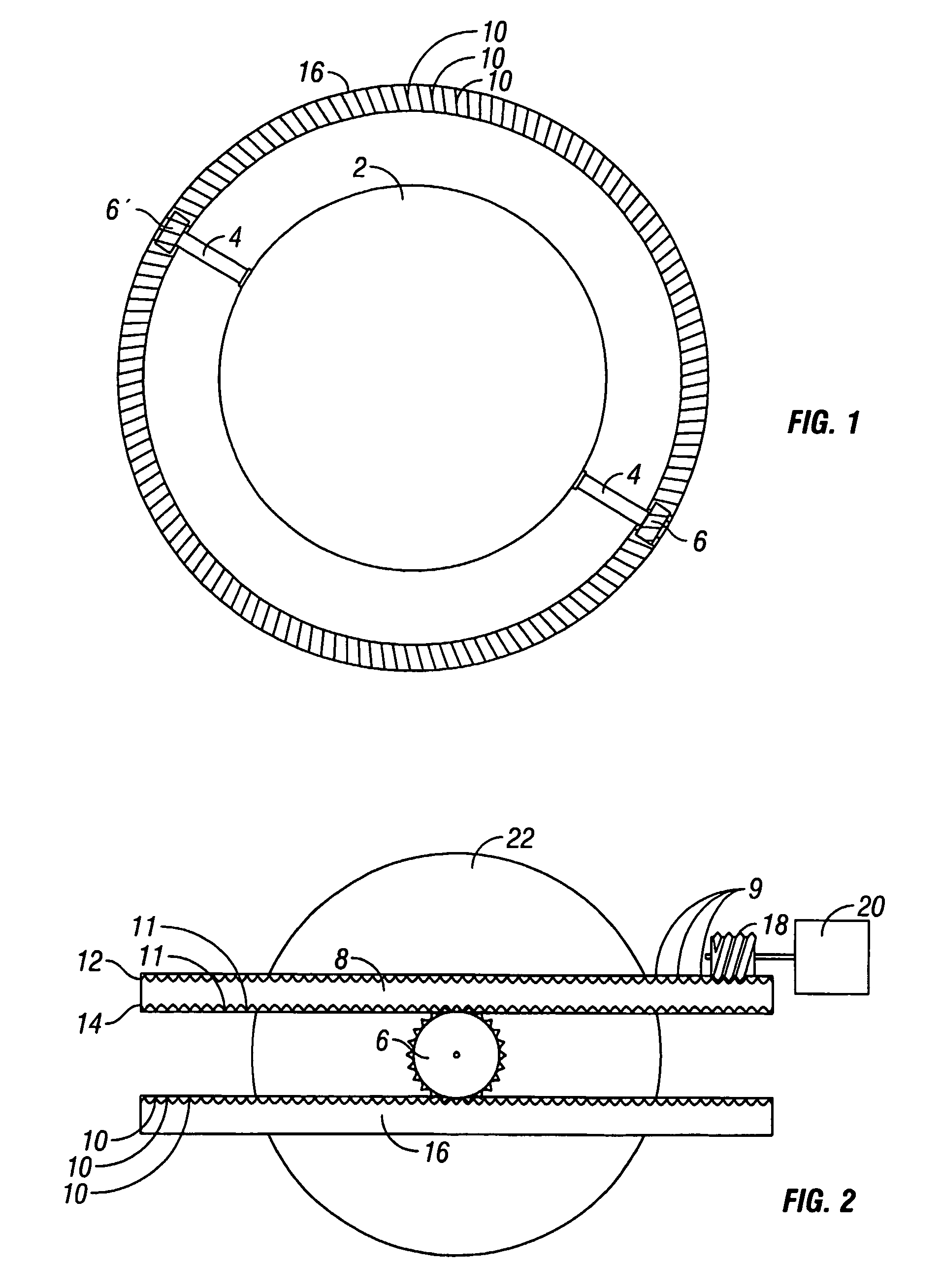
[0028] One embodiment of the present invention is illustrated in FIG. 1. In this embodiment, the action of the bi-axial rotation is accomplished by mounting a permanent magnet 2 on a rod 4 that has a drive gear 6, or other meshing or traction surface arrangement, attached at one end. Although a gear system is used in the preferred emb...


PUM


Abstract

A device for applying a time-varying magentic field to a human or animal body for therapeutic purposes comprising a magnetic body (72), housed in a free moving member (80), which is it-self housed within the device. The device is powered by a small electric motor that drives the free moving member (80) and magnetic body (72) to rotate about an exis of first rotation. The magnetic body is further caused to rotate around an axis of second rotation through angular forces imparted on it either mechanically or magnetically. Mechanical angular force is imparted by a gear and tooth arrangement or other similar tactile interaction with a roller member (106). Magnetic angular force is imparted by stationary magnets (110) as the magnetic body (72) rotates past them. The two rotational movements of the magnetic body (72) are oblique to one another and produce both a time-varying field of magnetic flux density and a time varying field of angular flux displacement.

Description

CROSS-REFERENCES TO RELATED APPLICATIONS [0001] This patent application is a continuation-in-part application of U.S. patent application Ser. No. 10 / 087,135, filed Feb. 28, 2002, which is incorporated by reference as if fully stated herein.TECHNICAL FIELD [0002] This invention relates generally to a magnetic field generating apparatus and more specifically to a magnetic field generating apparatus that produces a time-varying angular displacement of magnetic flux density for use in therapeutic applications on humans or on animals. BACKGROUND ART [0003] Various devices have been made to create time-varying magnetic fields for use on the human body. Generally, two types of time-varying magnetic fields have been used. The first type used an alternating current (“AC”) field that is produced when electric current is caused to alternate at any given frequency. In accordance with Maxwell's equations, a magnetic field is concurrently produced at the same frequency as the electric field. Incl...

Claims


Application Information

Patent Timeline
Patent Type & Authority Applications(United States)
IPC IPC(8): A01K13/00A61N2/00A61N2/12
CPCA61N2/12
Inventor ARDIZZONE, VINCENTBOVE, THOMAS
Owner ARDIZZONE VINCENT
Why Eureka
Try Eureka