Occipital plate and system for spinal stabilization

a technology of occipital plate and spinal stabilization, which is applied in the field of system for stabilizing the spine, can solve problems such as difficulties in achieving the desired fi

Inactive Publication Date: 2005-06-09
DEPUY SYNTHES PROD INC
View PDF6 Cites 132 Cited by
  • Summary
  • Abstract
  • Description
  • Claims
  • Application Information

AI Technical Summary

Problems solved by technology

In particular, because a traditional unitary plate and rod system is bent in two planes in order to properly adjust it with respect to the occiput, such a unitary design presents difficulties in achieving the desired fit.

Method used


Image

  • Occipital plate and system for spinal stabilization
  • Occipital plate and system for spinal stabilization
  • Occipital plate and system for spinal stabilization

Examples


Embodiment Construction

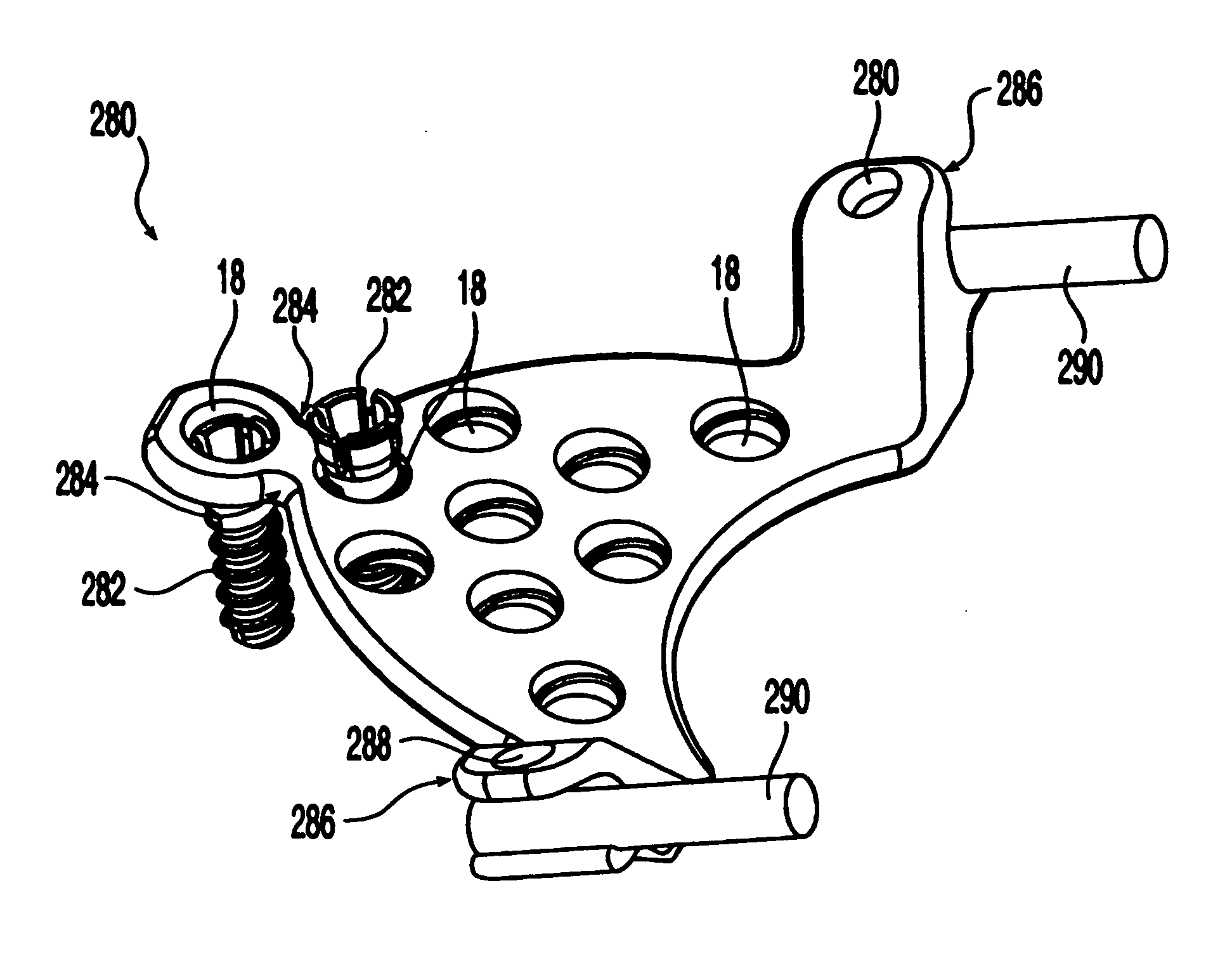
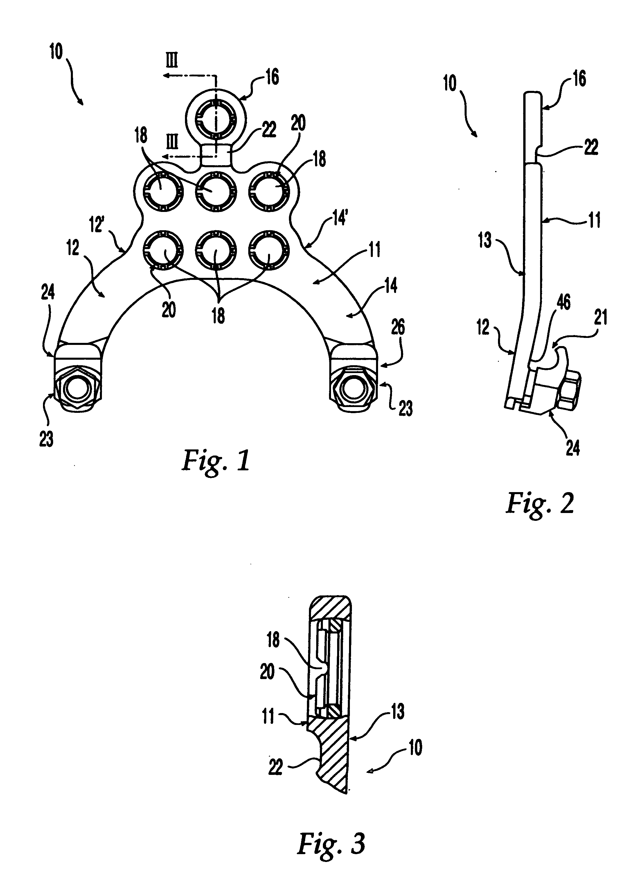
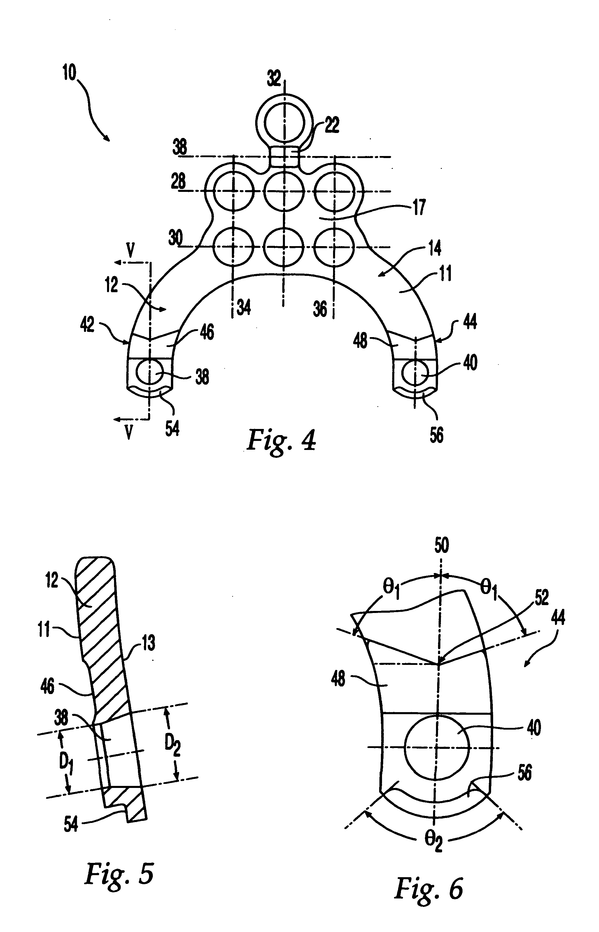
[0032] Referring initially to FIGS. 1-3, an occipital plate 10 according to the present invention is shown. In the preferred embodiment, occipital plate 10 is generally Y-shaped with a pair of rod supporting arms 12, 14 and a central extension 16 along with a main portion 17. Holes 18 extending from the front surface 11 to the back surface 13 are provided for receiving bone fasteners (not shown) for fixation of occipital plate 10 to the occiput. Preferably, as shown in FIG. 3, holes 18 are each provided with an expansion head bushing 20 to permit relative angulation of a locking screw or other bone fastener received therein. A grooved region 22 is provided along central extension 16 to facilitate bending of plate 10. In the preferred embodiment, plate 10 may be bent along grooved region 22. In an alternate embodiment, central extension 16 and grooved region 22 may be removed from plate 10. Preferably, grooved region 22 has a thickness that may be accommodated in a rod cutter as used...


PUM


Abstract

An occipitocervical fixation system includes a plate for securing to the occiput and at least one pre-bent rod. The plate includes holes for receiving bone fasteners, and at least one clamping assembly for retaining a portion of a rod. The clamping assembly is selectively pivotable and lockable in place to fix the position of the rod.

Description

[0001] This application is a continuation of and claims priority to U.S. patent application Ser. No. 09 / 788,639, filed Feb. 21, 2001, which is expressly incorporated by reference herein in its entirety.FIELD OF THE INVENTION [0002] The present invention is related to a system for stabilizing the spine. More particularly, the present invention is related to an occipitocervical fixation system that is mounted to both the occiput and spine. BACKGROUND OF THE INVENTION [0003] Occipitocervical fixation has been achieved using a variety of techniques which generally provide stabilization of the base of the skull with respect to the neck. In order to promote fusion, for example, bone struts formed of autogenous ribs or curved iliac crest struts have been fixed to the occiput and spinous processes, cervical laminae, or facets. Wires are used to fix the struts in place until bone fusion occurs. The thickness of the occiput varies, however, and thus the occiput is typically wired in regions o...

Claims


Application Information

Patent Timeline
Patent Type & Authority Applications(United States)
IPC IPC(8): A61B17/70A61B17/58A61B17/80A61F2/44
CPCA61B17/7055A61B17/8085A61B17/8047A61B17/7011
Inventor BERGER, ROGERGERBER, DAVIDEMCH, HANSJUERG W.BRACE, MICHAEL
Owner DEPUY SYNTHES PROD INC
Why Eureka
Try Eureka