Dynamic CMG array and method

a technology of cmg array and array, which is applied in the field of dynamic cmg array, can solve the problems of difficult or impossible to continue controlling the momentum and/or orientation of the spacecraft using the remaining cmg array, the mass properties of the spacecraft are not exactly, and the available momentum control space is generally much reduced. to achieve the effect of improving spacecraft control and facilitating rotation

Active Publication Date: 2005-06-09
HONEYWELL INT INC
View PDF15 Cites 9 Cited by
  • Summary
  • Abstract
  • Description
  • Claims
  • Application Information

AI Technical Summary

Problems solved by technology

A problem with prior art CMG arrays is that when one or more of the CMGs in the array fails, it is often difficult or impossible to continue controlling the spacecraft momentum and / or orientation using the remaining CMGs.
Even if some control continues to be possible, the available momentum control space is generally much reduced because the orientation of the remaining CMGs is no longer optimal.
A further problem often encountered with spacecraft is that upon construction or arriving in orbit, the mass properties of the spacecraft are not exactly as initially predicted, and the CMG orientation initially set up is less than optimum for the actual mass properties after construction or in arrival orbit.
A still further problem is that during the life of the spacecraft due, for example, to the expenditure of maneuvering fuel or other supplies or cargo released or captured, the mass properties of the spacecraft may change with time.
Once again, an initial CMG array orientation may no longer provide the maximum momentum control space.

Method used


Image

  • Dynamic CMG array and method
  • Dynamic CMG array and method
  • Dynamic CMG array and method

Examples


Embodiment Construction

[0014] The following detailed description is merely exemplary in nature and is not intended to limit the invention or the application and uses of the invention. Furthermore, there is no intention to be bound by any expressed or implied theory presented in the preceding technical field, background, brief summary or the following detailed description. The words “orthogonal” and “substantially orthogonal” are used herein in connection with the relative orientation of various rotation axes and / or vectors in three-dimensional (3-D) space. These words are intended to describe, merely by way of example, a preferred arrangement or embodiment and are not intended to be limiting. It is not necessary that the vectors or axes associated with the CMGs of the present invention be 90 degrees apart, merely that they not all be parallel.

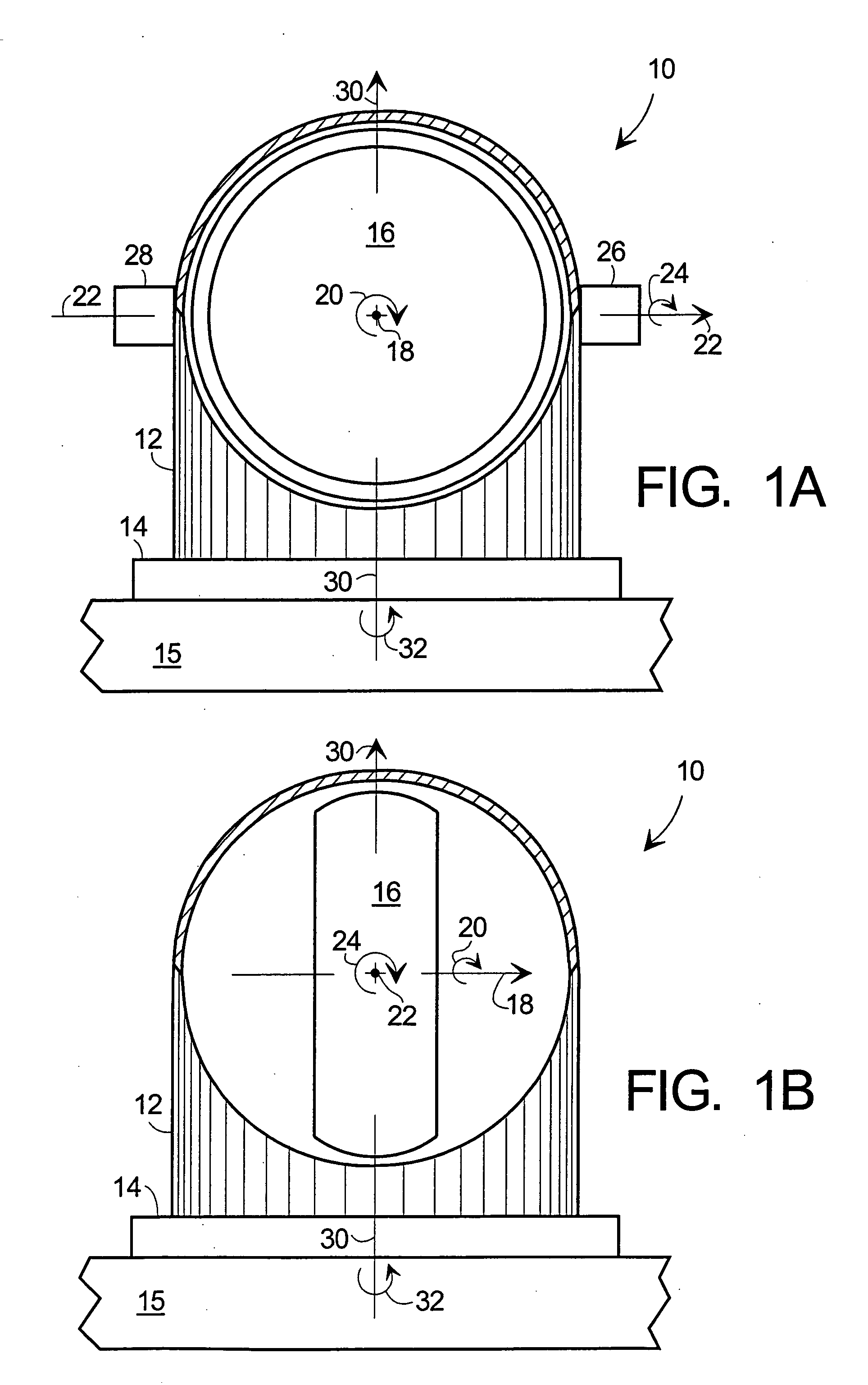
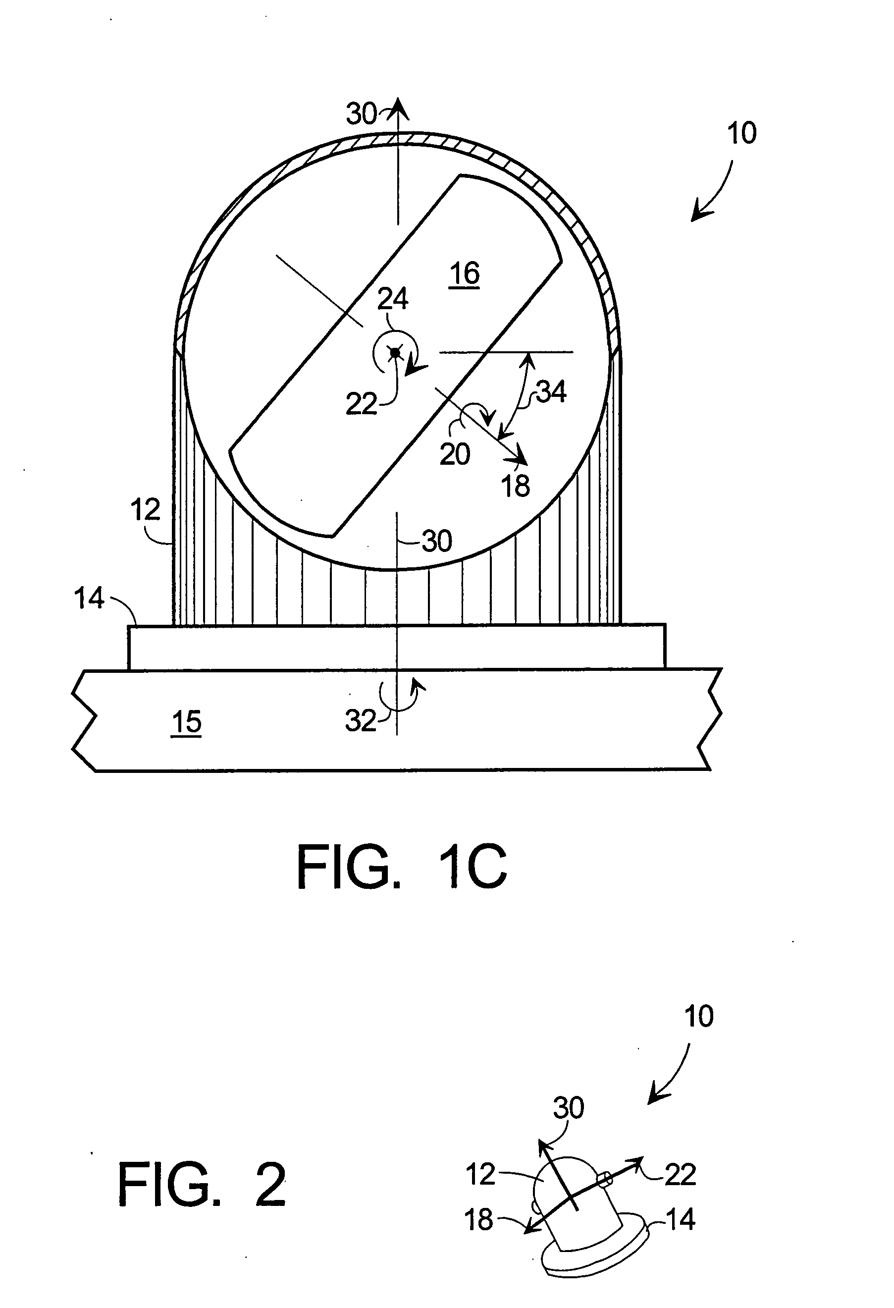
[0015]FIGS. 1A-1C are highly simplified partially cut-away schematic illustrations of CMG 10 according to the present invention. The internal elements of CMG 10 wit...


PUM


Abstract

Methods and apparatus are provided for reorienting control moment gyros (CMGs) to compensate for CMG failure or change in spacecraft (S / C) mass properties or mission. An improved CMG comprises a drive means for rotating the CMG around an axis not parallel to the CMG gimbal axis. Releasable clamps lock the CMG to the spacecraft except during CMG array reorientation. CMGs arrays are combined with attitude sensors, a command module, memory for storing data and programs, CMG drivers and sensors (preferably for each CMG axis), and a controller coupling these elements. The method comprises determining whether a CMG has failed or the S / C properties or mission changed, identifying the working CMGs of the array, determining a new array reorientation for improved spacecraft control, unlocking, reorienting and relocking the CMGs in the array and updating the S / C control parameters for the new array orientation.

Description

TECHNICAL FIELD [0001] The present invention generally relates to systems for controlling spacecraft momentum, and more particularly to spacecraft systems employing multiple controlled moment gyros (CMGs). BACKGROUND [0002] It is well known in the art to use control moment gyros (CMGs) to control the momentum and adjust the orientation of spacecraft. CMGs and momentum control systems are described, for example, in Patents or Patent Publications: US-2002 / 0040950 A1 to Staley et al; U.S. Pat. No. 6,231,011 B1 to Chu et al; U.S. Pat. No. 6,154,691 to Bailey; U.S. Pat. No. 6,360,996 B1 to Bockman et al; U.S. Pat. No. 6,128,556 to Bailey; U.S. Pat. No. 6,131,056 to Bailey et al; U.S. Pat. No. 6,285,927 B1 to Rongsheng et al; U.S. Pat. No. 6,305,647 B1 to Defendini et al; U.S. Pat. No. 6,039,290 to Bong Wie et al; and U.S. Pat. No. 6,311,931 B1 to Smay. It is known to use CMG arrays to adjust the momentum of the spacecraft and / or vary its orientation in three dimensions. [0003] A problem ...

Claims


Application Information

Patent Timeline
Patent Type & Authority Applications(United States)
IPC IPC(8): B64C1/00B64G1/28G01C19/06G01C19/30G05D1/08G06F7/00
CPCB64G1/286G01C19/065G01C19/30Y10T74/1221Y10T74/1204Y10T74/1218G05D1/0883B64G1/244
Inventor BONN, J. JEFFPECK, MASON A.
Owner HONEYWELL INT INC
Why Eureka
Try Eureka