Device for fixing a dust-collecting bag on a dust-collecting machine

Inactive Publication Date: 2005-06-16
SAN FORD MACHINERY
View PDF9 Cites 9 Cited by
  • Summary
  • Abstract
  • Description
  • Claims
  • Application Information

AI Technical Summary

Benefits of technology

[0009] A first objective of the invention is to offer a device for securing a dust-collecting bag on a dust-collecting machine, able to quickly and directly assemble a dust-collecting bag on a wind-exhausting box without help of any additional tightening component and firmly fix the dust-collecting bag on the wind-exhausting box by increase of a vacuum sucking force and also able to remove the dust-collecting bag from the wind-exhausting box with ease and with less force.
[0010] A second objective of the invention is

Problems solved by technology

The components of the clasping strap 14 are buckled with one another to be pulled and pressed;

Method used


Image

  • Device for fixing a dust-collecting bag on a dust-collecting machine
  • Device for fixing a dust-collecting bag on a dust-collecting machine
  • Device for fixing a dust-collecting bag on a dust-collecting machine

Examples


Example

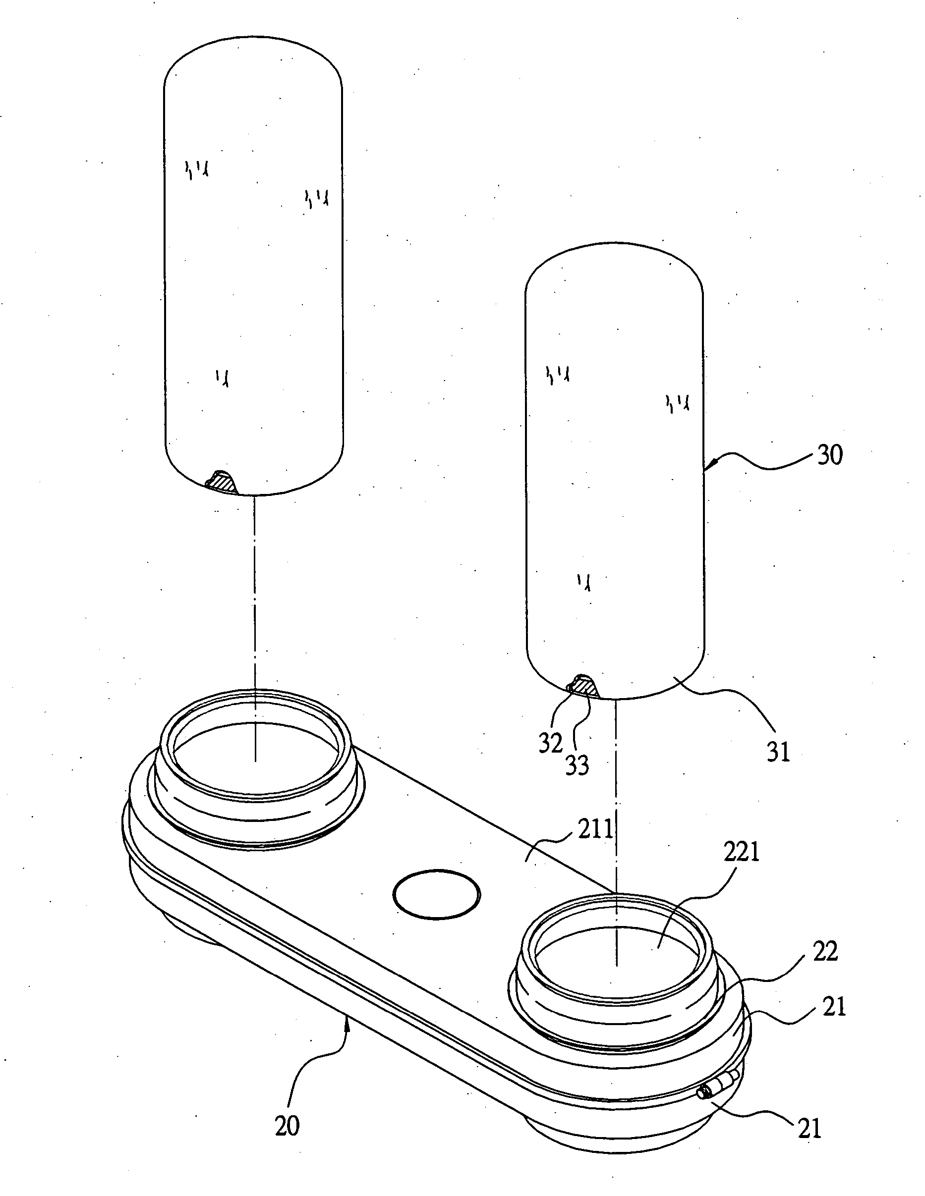
[0019] A preferred embodiment of a device for fixing a dust-collecting bag on a dust-collecting machine in the present invention, as shown in FIGS. 3 and 4, includes a wind-exhausting box 20 and two dust-collecting bags 30 combined together.

[0020] The wind-exhausting box 20 is provided with an upper and a lower cover 21 respectively having a horizontal base plate 211. The two horizontal base plates 211 have their circumferential edges respectively extending vertically to form a side wall 212 to be correspondingly combined: together and their opposite sides respectively bored with a through hole 213 having an annular fit base 22 provided thereon to form a wind-exhausting vent 221 for securing a dust-collecting bag 30 thereon.

[0021] The annular fit base 22, as shown in FIGS. 5 and 6, has its upper inner wall near the wind-exhausting vent 221 formed with a curved engage surface 222 shrinking inward gradually and then extending outward to form a curved expanding surface 223, which is ...


PUM

PropertyMeasurementUnit
Flexibilityaaaaaaaaaa
Resilienceaaaaaaaaaa

Abstract

A device for fixing a dust-collecting bag on a dust-collecting machine includes a wind-exhausting box having an annular fit base formed with a curved engage surface shrinking inward at the upper inner wall, and a dust-collecting bag having its opening portion wrapped therein with a flexible tightening ring. After slightly pressed inward and deformed, the opening portion of the dust-collecting bag is received in the annular fit base and the dust-collecting bag is pulled outward to make the tightening ring inside the opening portion firmly stuck on the curved engage surface by its expanding resilience. After the tightening ring is disengaged from the engage surface in the wind-exhausting vent, the dust-collecting bag can be removed from the wind-exhausting box, quick and easy in assembling with and disassembling from the annular fit base.

Description

BACKGROUND OF THE INVENTION [0001] 1. Field of the Invention [0002] This invention relates to a device for fixing a dust collecting bag on a dust-collecting machine, particularly to one having a simple structure and able to assemble a dust collecting bag on or disassemble it from a dust-collecting machine quickly. [0003] 2. Description of the Prior Art [0004] A conventional dust-collecting machine 10, as shown in FIG. 1, includes a wind-exhausting box 11 having a wind-exhausting vent 111 in its topside for fitting a dust-collecting bag 12 thereon and a fan motor 13 connected with the wind-exhausting box 11. Thus, when the fan motor 13 operates, dust can be sucked into the dust-collecting bag 12 through the wind-exhausting box 11. The dust-collecting bag 12 is fitted around the outer circumferential edge of the exhausting opening 111 of the wind-exhausting box 11 and has its opening portion 121 firmly secured thereon by means of a clasping strap 14 so as to fix the dust-collecting ba...

Claims


Application Information

Patent Timeline
IPC IPC(8): A47L5/38A47L9/14B01D46/00B01D46/02
CPCA47L5/38B01D46/02B01D46/0005A47L9/1427
Inventor CHENG, CHIEH YUAN
Owner SAN FORD MACHINERY
Why Eureka
Try Eureka