
Cutting assembly for removing a windshield and method relating to same

a technology of windshield and cutting assembly, which is applied in the direction of bird housing, portable percussive tools, cleaning of hollow objects, etc., can solve the problems of difficult cutting with tools, difficult to penetrate, and difficult to remove, and achieve the effect of sufficient lateral flexibility and rigidity

Inactive Publication Date: 2005-06-16
CRYSTAL GLASS CANADA
View PDF27 Cites 4 Cited by
  • Summary
  • Abstract
  • Description
  • Claims
  • Application Information

AI Technical Summary

Benefits of technology

The invention is a windshield removal assembly for vehicles that includes a reciprocating air gun, a rigid shaft, and a flat blade. The blade is connected to the shaft and is designed to cut through the urethane bed that secures the windshield to the vehicle. The blade is flexible enough to conform to the curved surface of the windshield but stiff enough to make precise cuts. The assembly is designed to be used within the confines of the space between the windshield and the vehicle's part. The method involves reciprocating the blade and severing the bed across its width, leaving a smooth cut surface. The technical effects of this invention include a faster and safer way to remove windshields, reduced damage to the bed, and a smoother cut surface.

Problems solved by technology

The urethane bed is hard and tough and not easily penetrated.
In use, these tools were characterized by several problems.
More particularly: Cutting with them was slow.
The depth and width of the cut were small, requiring a great many cuts to complete the job.
Typically it would take about 15-20 minutes to cut the windshield free; Using the prior art assemblies was laborious.
The installer would have to apply a sideways pull to these tools, particularly when cutting along the horizontal legs of the bed; It was common to crack the glass when first penetrating the bed.
This could leave broken glass on the dash and elsewhere, which was undesirable; The cuts made by the tools were shallow.
This meant that at the corners, where the bed width was greatest, it would take prolonged cutting to complete severing the bed.
In the course of hand cutting the corners, the installer would commonly press hard with his head against the windshield to assist his cutting—this was known to lead to neck injuries; The cut surface produced by the blades of these powered tools was irregular (jagged and undulating).
This was undesirable as the newly extruded bead would in part reproduce this underlying irregularity and the new windshield would then not seat flush against the bed surface.
This could lead to a poor seal and subsequent leaking; The electric motor-driven tools of the prior art were generally bulky and difficult to work with in confined space, such as the apex between the vehicle dashboard and the inside surface of the windshield; The prior art blades were fragile and expensive—breakage was a problem; and It was necessary to use soapy water as a coolant and lubricant for the narrow, rapidly moving blades.
After the cut was complete, the cut surface needed to be carefully washed to remove soap, as it was detrimental to getting a good bond when new urethane was laid on.

Method used


Image

  • Cutting assembly for removing a windshield and method relating to same
  • Cutting assembly for removing a windshield and method relating to same
  • Cutting assembly for removing a windshield and method relating to same

Examples


Embodiment Construction

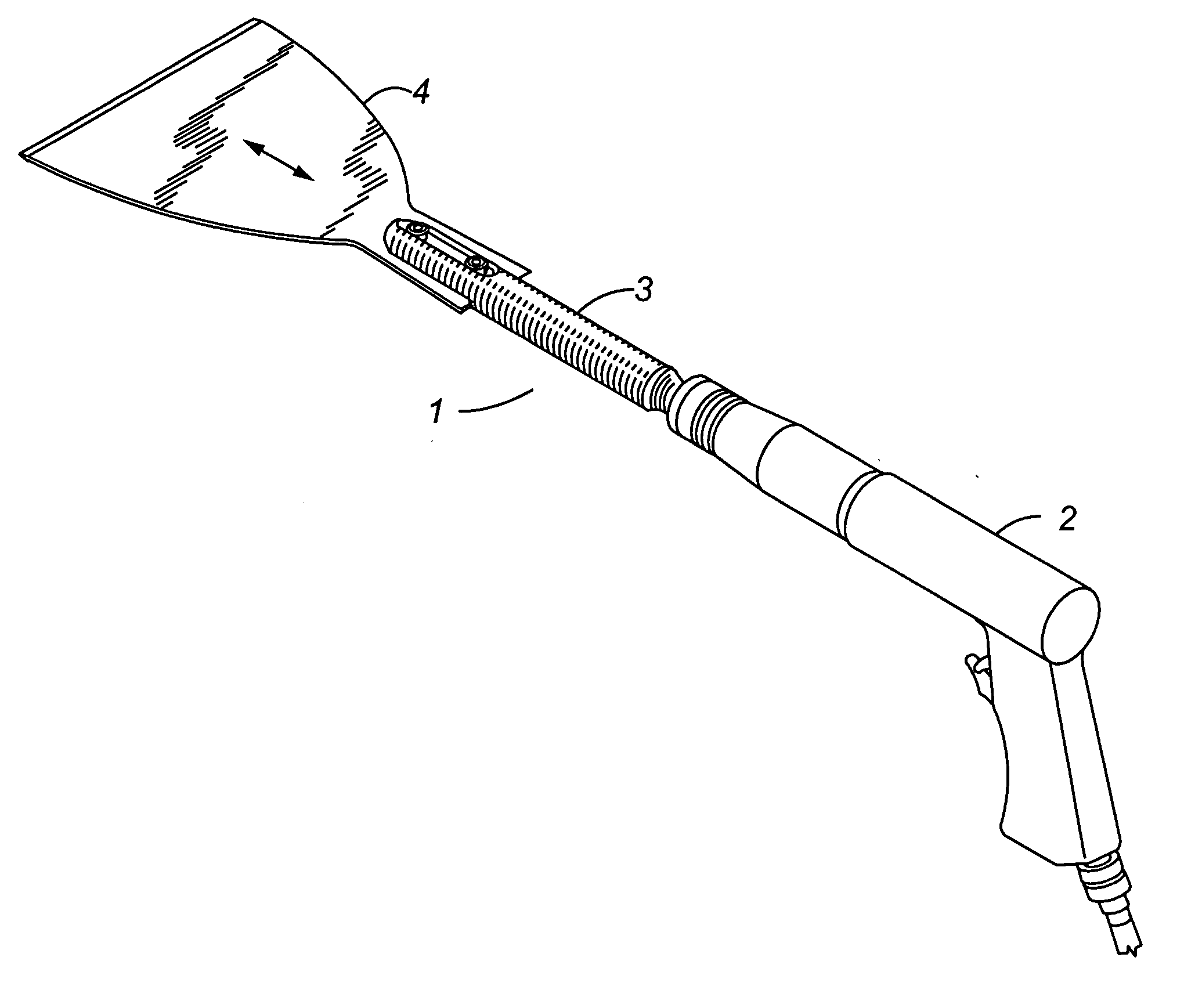
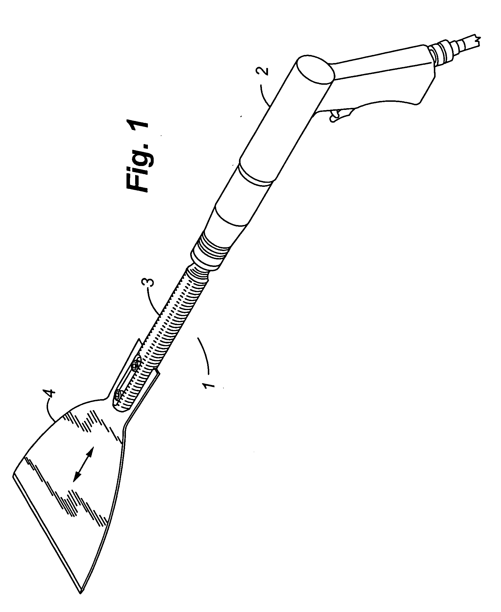
[0039] The cutting assembly 1 comprises a reciprocating air gun 2 and a cutting tool comprised of a shaft 3 and blade 4.

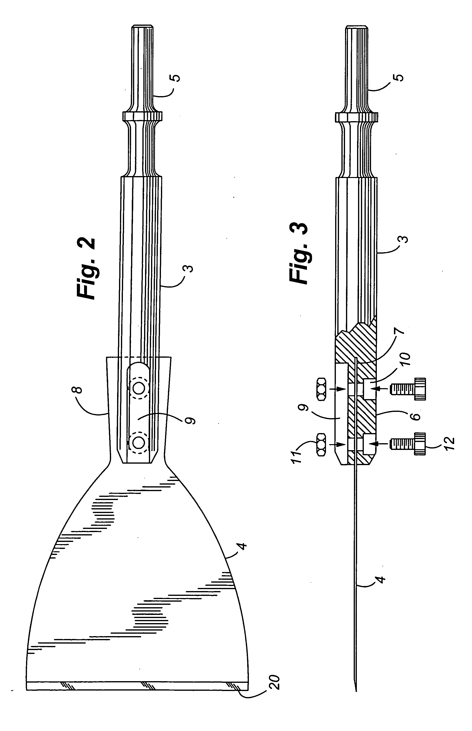
[0040] The air gun 2 is commercially available. An Ingersoll Rand Pneumatic model #117 or a Chicago Pneumatic model # CP715 gun is suitable. These guns can deliver high impact strokes to advance the blade 4 through the urethane bed 24. The shaft 3 is a {fraction (3 / 4)} inch diameter steel rod having an inner end 5 conventionally shaped to connect with the air gun 2. At its outer end 6, a slot 7 extends inwardly to receive the shank 8 of the blade 4. The upper surface of the rod end 6 forms a recess 9. The rod end 6 further forms bolt holes 10 extending transversely therethrough. Nuts 11 and bolts 12 are received in the recess 9 and holes 10 to secure the blade shank 8 to the rod end 6.

[0041] The blade 4 is substantially bell-shaped, is formed of stainless steel, has a width at the front edge 20 of about 4 inches, a length of 6 inches and a thickness of 0.05 inche...


PUM

PropertyMeasurementUnit
widthaaaaaaaaaa
widthaaaaaaaaaa
lengthaaaaaaaaaa

Abstract

The cutting assembly functions to sever the urethane bed bonding a windshield to a vehicle. The assembly comprises a reciprocating air gun connected with a cutting blade by a shaft. The blade has a straight front cutting edge about 4 inches in width. The blade is reciprocated in and out of the bed to sever it.

Description

CROSS REFERENCE TO RELATED APPLICATIONS [0001] This application is a divisional of prior pending U.S. patent application Ser. No. 09 / 633,074 filed Aug. 4, 2000, which is a continuation of U.S. patent application Ser. No. 08 / 781,954 filed Dec. 2, 1996. The entire disclosures of the prior applications are incorporated herein it their entireties.FIELD OF THE INVENTION [0002] This invention relates to an assembly and method for separating a glass windshield from a vehicle urethane bed by severing the bed along its length. BACKGROUND OF THE INVENTION [0003] In the process of securing a glass windshield to a new car or truck, the manufacturer first extrudes a bead or “bed” of urethane onto the “pinch weld” extending around the perimeter of the window opening. The urethane bed bonds to the pinch weld surface. The glass windshield then is seated on the bed and bonds to it, forming a liquid-tight seal. [0004] The urethane bed is hard and tough and not easily penetrated. It commonly has a thi...

Claims


Application Information

Patent Timeline
Patent Type & Authority Applications(United States)
IPC IPC(8): B23D67/04B25D17/00B25D17/02B60J10/00B60J10/02
CPCB23D67/04B25D17/005B25D17/02B25D2222/69B60J10/0088B60J10/02Y10T156/1911Y10S83/945Y10S156/927Y10T156/1961Y10T156/1168Y10T156/1972Y10S156/939B60J10/45B60J10/70Y10T83/242Y10T83/0443Y10T83/04
Inventor OGSTON, ALFRED JOHN
Owner CRYSTAL GLASS CANADA
Learn More