
Fuel supply device

a fuel supply device and fuel tank technology, applied in the direction of cycle equipment, machines/engines, cycles, etc., can solve the problems of small fuel tank capacity, difficult to form a flat surface, and difficult to mount the fuel pump on the bottom plate side of the fuel tank, etc., and achieve the effect of small capacity

Inactive Publication Date: 2005-06-16
HONDA MOTOR CO LTD
View PDF16 Cites 46 Cited by
  • Summary
  • Abstract
  • Description
  • Claims
  • Application Information

AI Technical Summary

Benefits of technology

[0007] It is an object of the present invention to provide a fuel supply device which can mount a fuel pump inside a fuel tank with a bottom portion that has a complicated shape or a fuel tank that has a small capacity.
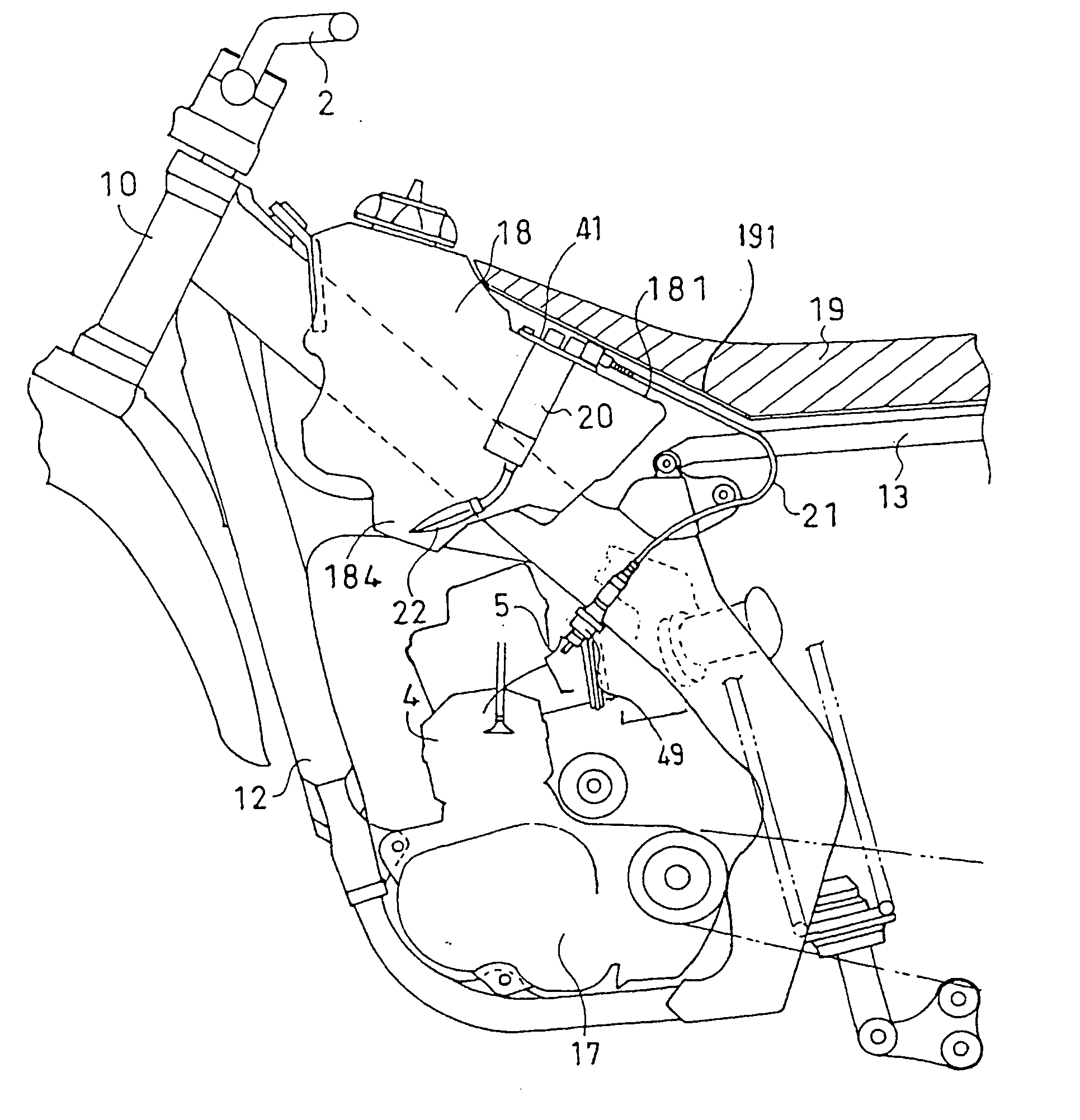
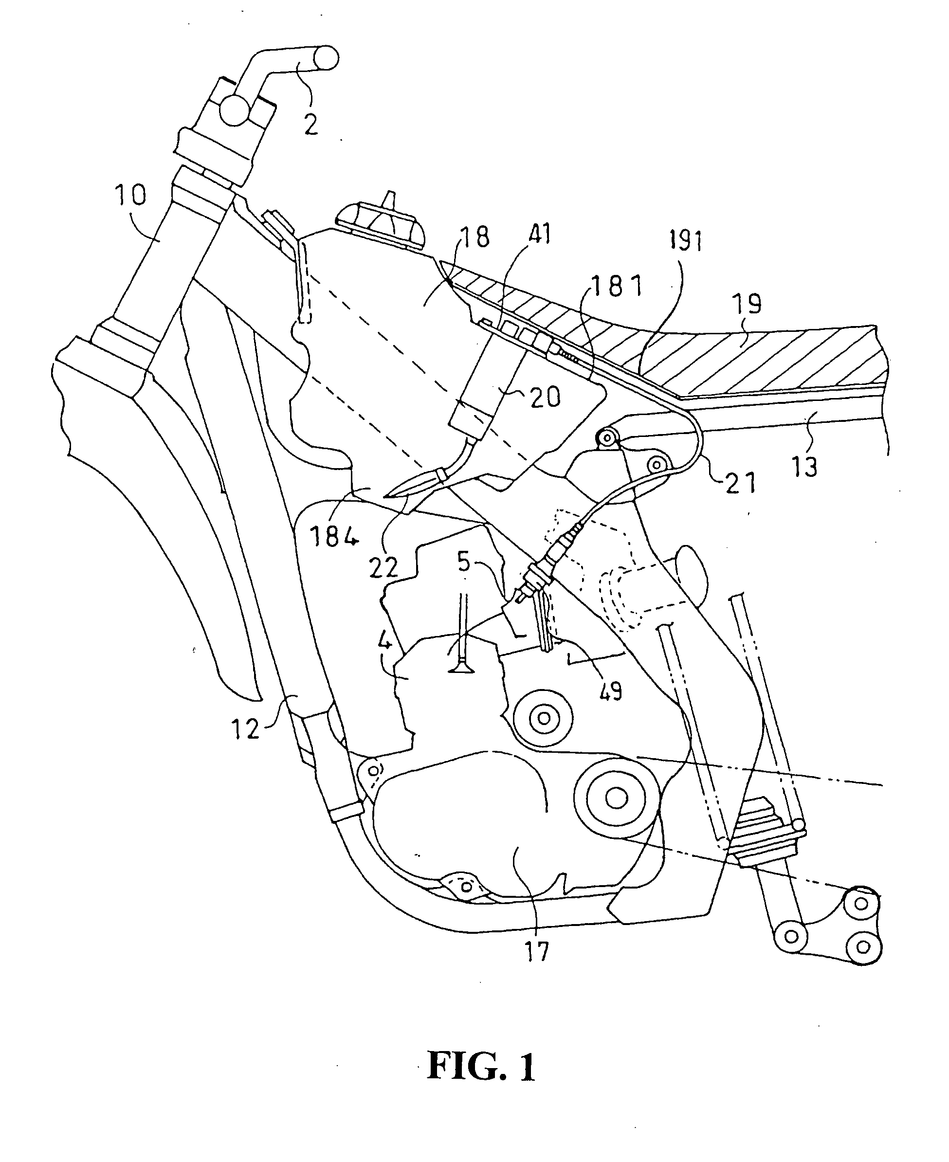
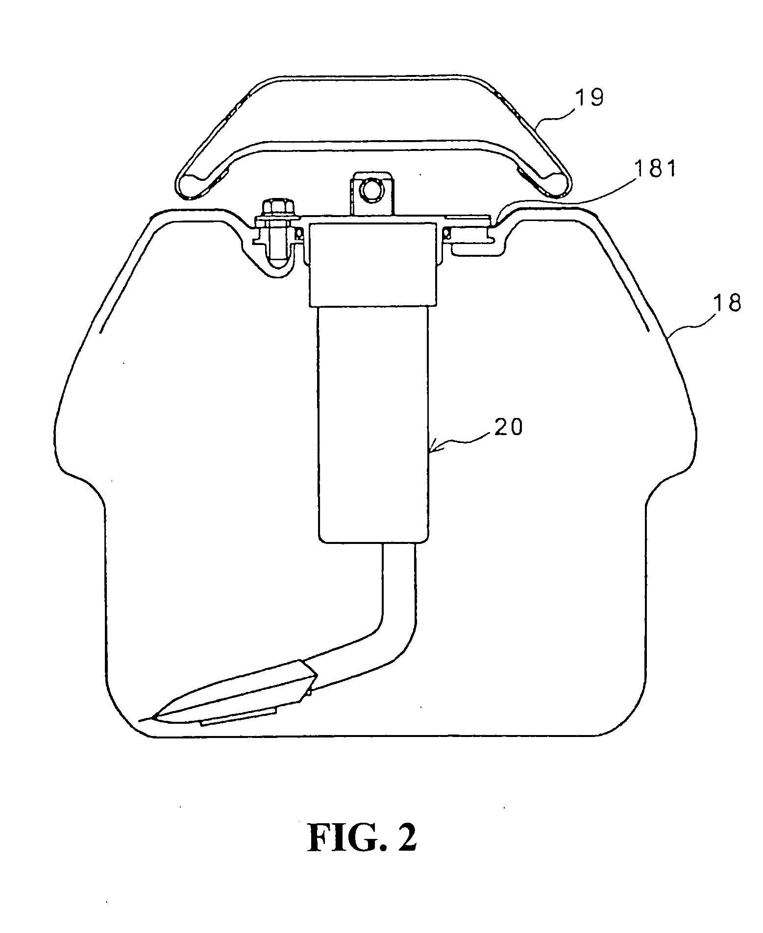
[0012] According to the present invention having the first feature, since the fuel pump is arranged inside the fuel tank in a downwardly suspended manner from the upper surface of the fuel tank, it is possible to easily mount the fuel pump inside the fuel tank even when the width thereof is small and the bottom portion thereof has a complicated shape. Further, although the discharge joint of the fuel and the power supply connector which are positioned on the upper surface of the fuel tank are covered by the rider's seat, these portions are provided to an appearance portion which is exposed from the fuel tank. Thus, the maintenance of these portions is facilitated.
[0013] With respect to an offroad vehicle, in general, the width of the fuel tank is small and the shape thereof is complicated. Thus, by applying the present invention to the offroad vehicle having such a fuel tank, it is possible to easily perform the fuel pump mounting operation.
[0015] According to the fourth feature, the fuel pump has an elongated shape and has no portion which projects from an outer diameter of a pump body. Thus, it is possible to easily incorporate the fuel pump inside the fuel tank having a small width and a complicated shape.

Problems solved by technology

However, with respect to a motorcycle of an offroad model or a racing model, it is often the case that the capacity of the fuel tank is small or it is difficult to form a flat surface on the bottom plate.
Accordingly, in such a vehicle, it is difficult to mount the fuel pump on the bottom plate side of the fuel tank.

Method used


Image

  • Fuel supply device
  • Fuel supply device
  • Fuel supply device

Examples


Embodiment Construction

[0030] One embodiment of the present invention is explained hereinafter in conjunction with drawings. FIG. 5 is a side view of a motorcycle of an offroad model having a fuel supply device according to one embodiment of the present invention. Here, in the embodiment explained hereinafter, the explanation is made with respect to an example in which the present invention is applied to the motorcycle of an offroad model. In this embodiment, the offroad model or the offroad vehicle is not limited to a two-wheeled vehicle but can include a two-wheeled vehicle, a three-wheeled vehicle or a four-wheeled vehicle which travels on an uneven ground and a so-called buggy vehicle.

[0031] In FIG. 5, the motorcycle 1 is provided with a vehicle body frame which includes a head pipe 10 which is positioned at the front portion of the vehicle body, main frames 11 which extend rearwardly and downwardly from the head pipe 10, and a lower frame 12 which has a front end thereof connected to lower ends of t...


PUM


Abstract

To incorporate a fuel pump inside a fuel tank having a complicated shape with a small width. A motorcycle may be an offroad model with a fuel tank having a complicated shape with a small width. The fuel pump includes a base plate which is fixed to a plate fitted on the upper surface of the fuel tank. A cylindrical and elongated pump body extends downwardly from the base plate. An intake pipe having a filter formed on the distal end thereof is connected to the pump body. The base plate of the fuel pump and a hose joint arranged on the upper surface of the base plate are covered by the front portion of the rider's seat. The upper portion of the fuel pump is exposed to the outside of the fuel tank. Thus, it is possible to easily have access to the fuel pump when performing the maintenance.

Description

CROSS-REFERENCE TO RELATED APPLICATIONS [0001] The present application is related to Japanese Patent Application No. 2003-414847 filed on Dec. 12, 2003 the entire contents of which are hereby incorporated by reference. BACKGROUND OF THE INVENTION [0002] 1. Field of the Invention [0003] The present invention relates to a fuel supply device, and more particularly to a fuel supply device for a vehicle wherein a fuel pump is positioned inside a fuel tank which is small and has a small width. [0004] 2. Description of Background Art [0005] In mounting a fuel pump inside a fuel tank, the fuel pump is often mounted on the bottom plate side of the fuel tank. For example, JP-A-11-93794 discloses a fuel supply device for a vehicle wherein a base plate of a fuel pump is fixed to a flattened portion formed on the rear end portion of a bottom plate of a fuel tank. Further, JP-A-2002-106440 discloses a fuel supply device for a vehicle wherein a fuel pump is provided inside a fuel tank with the fue...

Claims


Application Information

Patent Timeline
IPC IPC(8): B62J37/00F02B61/02F02M37/00B62J35/00F02M37/10F02M37/22
CPCB62J35/00B62J37/00F02M2037/228F02M37/103F02B61/02F02M37/50
Inventor YAGISAWA, KATSUICHI
Owner HONDA MOTOR CO LTD
Learn More