
Method, system and devices for data acquisition

a data acquisition and data technology, applied in the field of data acquisition, can solve the problems of difficult implementation of requirements in a single generic product, short response time in any such communication, and limited communication distance of passive tags

Active Publication Date: 2010-12-09
CONTROLMATIC
View PDF11 Cites 65 Cited by
  • Summary
  • Abstract
  • Description
  • Claims
  • Application Information

AI Technical Summary

Benefits of technology

[0009]An object of the present invention is to provide a data acquisition method, system and devices wherein the described disadvantages of the prior art are avoided or reduced.
[0010]The object of the invention is therefore to provide technology wherein reliable data transfer and long operating cycles are achieved without a frequent requirement for recharging or changing batteries of RFID devices.
[0012]In the inventive solution it is possible to keep the receiver active for only short periods because it is not necessary to detect and process data transmitted from the master device in order to start the transmission of data from the RFID device.
[0044]The present invention offers important advantages over the prior art. The RFID device is not required to receive continuously data from the RF channel, so the receiver can remain in a power saving mode for a large percentage of time. In the power saving mode, the operating current may be switched off from the processor, receiver and transmitter circuits. This way low average power consumption is achieved. As a result, it is possible to use batteries of relatively small capacity, size and cost. Due to the non-frequent servicing requirement, it is also possible to achieve high functional reliability of the RFID device. Due to the long operating time and small size of a tag, it is also possible to install the RFID devices into locations in which servicing of the tag would be difficult. Also, the small size of the batteries as well as the non-frequent replacement requirement of the batteries decreases any possible impact on the environment.
[0045]It is also an advantage that the transmission of the data from an RFID device does not have to be dependent on the communications from a second device to the RFID device. For example, if there is some fault in the transmission function or ciphering function in the second device, or a fault in the receiving functions of the RFID device, it is still possible to transfer the acquired data from the RFID device to the second device. It is also not necessary to provide any registration of an RFID device into the network of the system. Thus any power consumption related to such functions can be avoided.

Problems solved by technology

Active tags may have a range of hundreds of meters whereas passive tags are limited to much shorter communication distances.
Such requirements are not particularly easy to implement in a single generic product, and the product development in the field has diverged into multiple directions depending on each application dictating its own requirements and preferences.
Also, the response delays in any such communications are required to be very short.
However, such requirements also mean that the RF transceiver parts of the devices have high current consumption.
In RFID applications, however, current consumption is an important issue, and therefore the high rate communication channels are generally not suitable for communication between RFID tags and a master device.
However, this prior art solution also includes a problem concerning current consumption of the RFID devices.
However, an RF transceiver has generally an essential consumption of power in its active state, and therefore, long operation times would require batteries of large size and high cost in the RFID devices.

Method used


Image

  • Method, system and devices for data acquisition
  • Method, system and devices for data acquisition
  • Method, system and devices for data acquisition

Examples


Embodiment Construction

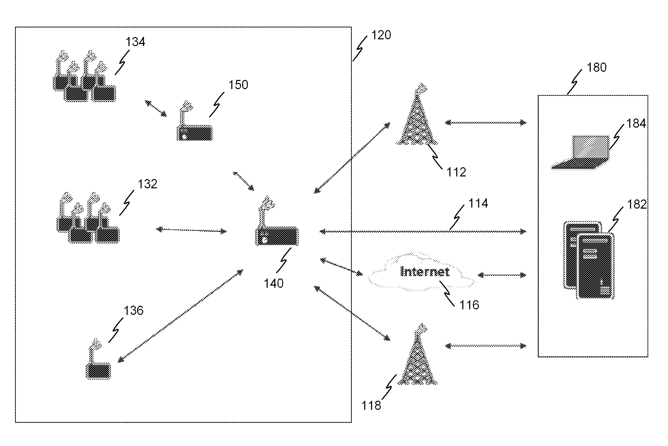
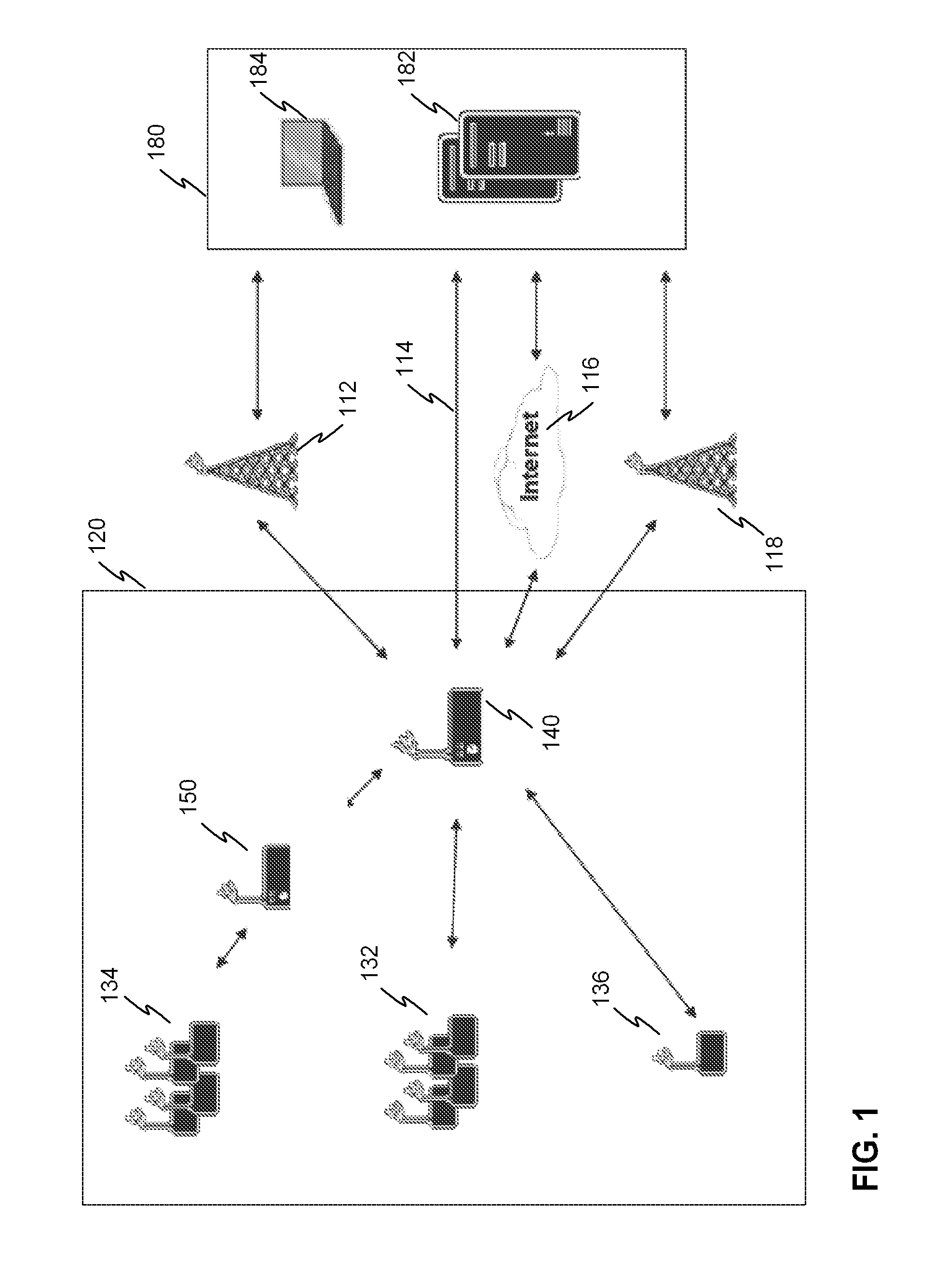
[0058]FIG. 1 illustrates an exemplary embodiment of a system according to the invention. The system has a plurality of RFID devices such as RFID devices 132-136. The RFID devices communicate with a master device 140 and / or a router 150 of the system.

[0059]The system has a first group 132 of RFID devices which are located at such a distance from the master device that a normal transmission power of the RFID devices is sufficient for the communications with the master device.

[0060]The system also has a second group 134 of RFID devices which are located at such a distance that the normal transmission power of the RFID devices is not sufficient for the communications directly with the master device 140. For the communications the system also has a router device 150 which is located between the locations of the group 134 and the master device 140. The purpose of the router is to collect data from the group 134 of RFID devices and forward the data to the master device. The distance betwee...


PUM


Abstract

The present invention relates generally to acquisition of data from RFID devices (132-136), such as sensor data. Prior art systems of active RFID devices have a problem of high average power consumption, and therefore, the energy source of the RFID devices needs to be replaced or charged frequently. The present invention provides a new solution wherein the RFID device has a power saving mode in which the receiver of the RFID device has a decreased ability to receive / detect RF signals. The RFID device may include a timer which is functional during the power saving mode, and the receiver of the RFID device will turn into active mode at a point of time based on the time value of the timer. Signal strength of an RF channel is indicated with a receiver, and transmission of data is dependent on the indication of the signal strength.

Description

FIELD OF THE INVENTION[0001]The present invention relates generally to acquisition of data from RFID devices, such as sensor data. More specifically, the present invention relates to what is disclosed in the preamble of the independent claims.BACKGROUND[0002]RFID technology concerns identification techniques enabling remote data retrieval via radio frequencies from RFID devices hereinafter also referred to as “tags”. The tags can be included in or attached to target objects such as different kinds of products or humans / animals that are to be identified. In addition to mere identifying a tag may incorporate or it may at least be functionally connected to one or more sensors providing measurement data to be passed forward by the communication means of the tag. A device called an RFID reader comprises an RF transceiver, or at least a receiver in the case of active tags described hereinafter, which can be used to remotely acquire the data from the tag whereby the physical distance betwe...

Claims


Application Information

Patent Timeline
IPC IPC(8): G06K7/01
CPCH04L1/188H04W24/00Y02B60/50H04W48/16H04W52/0245H04W28/04G06K19/0705H04W40/00Y02D30/70G06K7/0008G06K19/0723
Inventor LAURONEN, MIKA
Owner CONTROLMATIC
Learn More