Spark-emitting device for a skateboard

a technology of spark-emitting device and skateboard, which is applied in the direction of skateboards, vehicle components, sport apparatus, etc., can solve the problems of less than desirable spark-emitting concentration of spark-emitting device, and the inability of observers to satisfy the riders of skateboards, so as to achieve superior spark-emitting concentration, prolong the service life, and maximize the effect of spark-emitting length

Inactive Publication Date: 2005-06-16
RICHARDSON BRYSON +1
View PDF8 Cites 23 Cited by
  • Summary
  • Abstract
  • Description
  • Claims
  • Application Information

AI Technical Summary

Benefits of technology

[0010] The spark-emitting device of the present invention solves the above-mentioned problems by providing a unique sparking device composed of a misch metal alloy placed within a housing and attached to any part of a skateboard via double-sided tape. The housing is preferably made of a plastic material with a plurality of misch metal barrels inserted into respective openings within the housing. Preferably, the housing is composed of a polycarbonate material to provide a sufficient wear rate relative to the misch metal barrels.
[0011] To obtain the desired effect of having a superior concentration of sparks emitted from the device, as well as providing for a proper “wearing” of the misch metal barrels and the housing so that the misch metal barrels are not prematurely released from their openings within the housing, the present inventors have discovered that the spacing between adjacent misch metal barrels relative to the diameter of the barrels and the spacing between the barrels and edges of the housing are critical to the wearing of the device and the length and concentration of the sparks emitted therefrom. Accordingly, the width of the housing material located between adjacent barrels is preferably at most ⅓ of the diameter of the misch metal barrel. Most preferably, the width of the housing material located between adjacent barrels is approximately ⅙ of the diameter of the barrels. Likewise, the width of the housing material between the barrels and edges of the housing is also preferably at most ⅓ of the diameter of the barrels, and most preferably approximately ⅙ of the diameter of the barrels. With these ratios, the wearing of the housing material and the misch metal barrels, as well as the length and contraction of the sparks emitted, is maximized.

Problems solved by technology

One of the main drawbacks to the pyrotechnic device disclosed in the '407 patent is that, because of the configuration and spacing of the vertical integral fins, the concentration of the sparks emitted from the pyrotechnic device are less than desirable.
In particular, the concentration of the sparks emitted from the pyrotechnic device do not produce a satisfying effect for the riders of the skateboard, or the observers.

Method used


Image

  • Spark-emitting device for a skateboard
  • Spark-emitting device for a skateboard
  • Spark-emitting device for a skateboard

Examples


Embodiment Construction

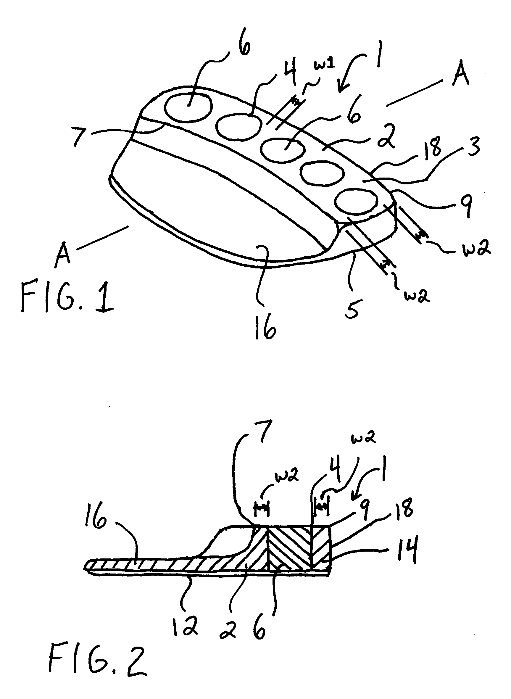
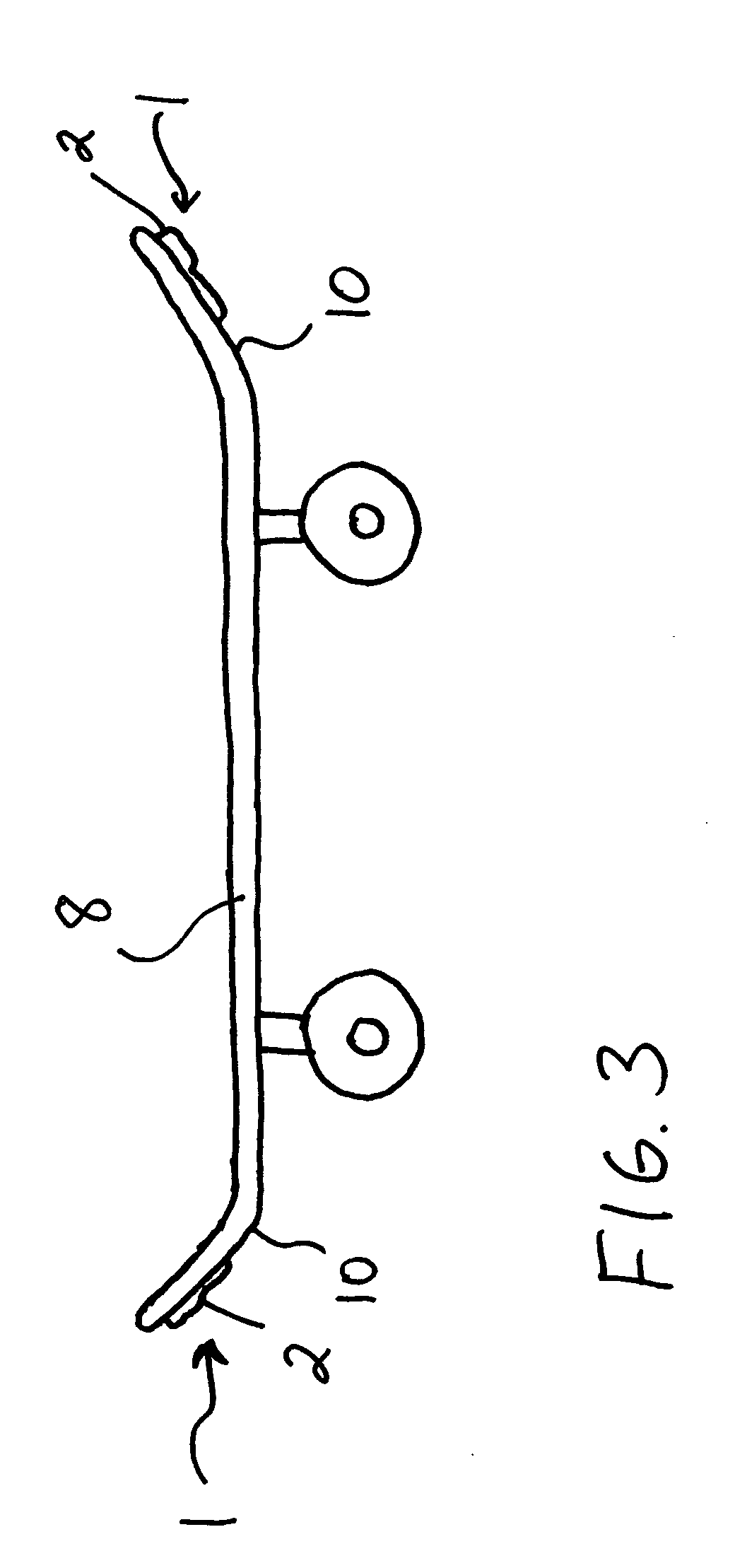
[0017] Referring now to the drawings, wherein like reference numerals represent like elements, FIGS. 1-3 show a preferred embodiment of the spark-emitting device of the present invention.

[0018] As described herein, the spark-emitting device of the present invention uses a special flint-like material which is sufficiently soft to emit elongated sparks, yet hard enough to wear slowly and not break under pressure or abrasion. Thus, due to the arrangement of the spacing of the misch metal barrels and the material used for the housing, the desired combination of wear rate and spark concentration is achieved. In addition, the misch metal barrel material is designed so as to maintain a low heat level in use so as to not melt the plastic base.

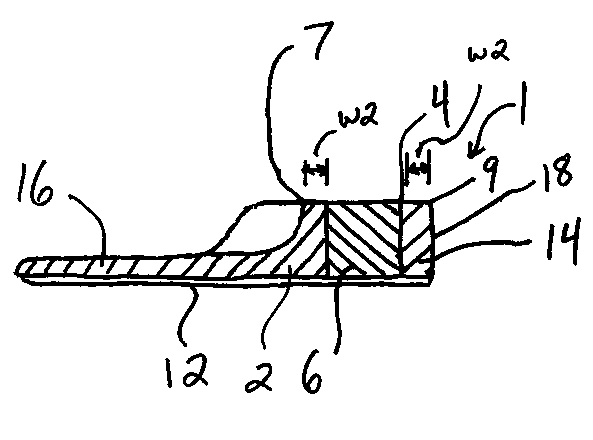
[0019] As shown in FIGS. 1-2, the spark-emitting device 1 comprises a housing 2 having an upper surface 3 and a lower surface 5 having a plurality of openings 4 therein which extend from the upper surface 3 proximate to the lower surface 5. Respectiv...


PUM


Abstract

A spark-emitting device for a skateboard. The spark-emitting device includes a housing and a plurality of misch metal barrels inserted into a housing and spaced apart so that the wear rate of the housing in the misch metal barrels is compatible and a desired sparking effect is achieved.

Description

CROSS REFERENCE TO RELATED APPLICATION [0001] The present application claims priority to U.S. Provisional Patent Application Ser. No. 60 / 530,473, filed Dec. 16, 2003, the entire contents of which are incorporated herein by reference.BACKGROUND OF THE INVENTION [0002] 1. Field of the Invention [0003] The present invention is directed to a spark-emitting device that attaches to any part of a skateboard and upon contact with any abrasive surface, emits a sparking effect. [0004] 2. Description of the Related Art [0005] Skateboarding is the fastest growing “extreme” sport in the U.S. since 1998. This growth has occurred because of the overall action sports trend, the activity's appeal as a spectator sport, expanding TV coverage for skateboarding, and its high visibility in the videogame market. [0006] Many of the maneuvers performed by a skateboard require abrupt changes in direction and / or speed. In a blur of flying acrobatics, skaters leap and skid over and onto obstacles, executive fl...

Claims


Application Information

Patent Timeline
Patent Type & Authority Applications(United States)
IPC IPC(8): A63C17/01
CPCA63C2203/14A63C17/01
Inventor KUHLMAN, JAMESCABLAYAN, FRANCISCO
Owner RICHARDSON BRYSON
Why Eureka
Try Eureka