Static magnetic field applying structure for use in atomic oscillator

a technology of atomic oscillator and applying structure, which is applied in the direction of oscillator, pulse automatic control, maser, etc., can solve the problems of affecting the operation of the static magnetic field generating circuit, the inability to design, and the inability to control the structure arrangement, etc., to achieve the effect of reducing the cost of production, facilitating the design of the structure, and facilitating the design

Inactive Publication Date: 2005-06-16
FUJITSU LTD
View PDF9 Cites 17 Cited by
  • Summary
  • Abstract
  • Description
  • Claims
  • Application Information

AI Technical Summary

Benefits of technology

[0038] According to the above inventions, plural sets of magnetic field generating means (solenoid coil) are combined for creating a static magnetic filed in a space sandwiched between the solenoid coils. Alternatively, a wire is wound to form a solenoid coil around a metal rod having antenna portions at both the end thereof and the static magnetic field is created in the space sandwiched between the antenna portions. Therefore, the static magnetic field generating means composing the atomic oscillator can be small-sized and produced at a low cost. Moreover, unlike the prior arts, the static magnetic field applying structure of the present invention need not have a layered structure in which the resonance cell is provided in a space surrounded with the solenoid coil. Therefore, the atomic oscillator will have greater freedom in designing the mechanical arrangement thereof, and hence the atomic oscillator can be further small-sized, the structure thereof can be further simplified, with the result that great contribution can be expected in low-cost production of the atomic oscillator.

Problems solved by technology

A problem we will encounter at this time is how the static magnetic field generating circuit shall be handled.
Therefore, layered structure is requested for the static magnetic field generating circuit, with the result that the structure thereof necessarily becomes complicated and freedom of structure arrangement is limited.
This fact becomes a problem to be solved when further small-sizing and low-cost production are carried forward.
Therefore, to increase the thickness of the wire winding portion is unavoidable.
For this reason, the solenoid coil frequently encounters limitation in the winding allowance portion around which the wire is wound.
As a consequence, parts constituting the solenoid coil are complicated and high-cost.
Accordingly, cost increase is unavoidable.
Therefore, the mounting area reduction is also limited.
Accordingly, cost increase is unavoidable.

Method used


Image

  • Static magnetic field applying structure for use in atomic oscillator
  • Static magnetic field applying structure for use in atomic oscillator
  • Static magnetic field applying structure for use in atomic oscillator

Examples


first embodiment

[B] Description of First Embodiment

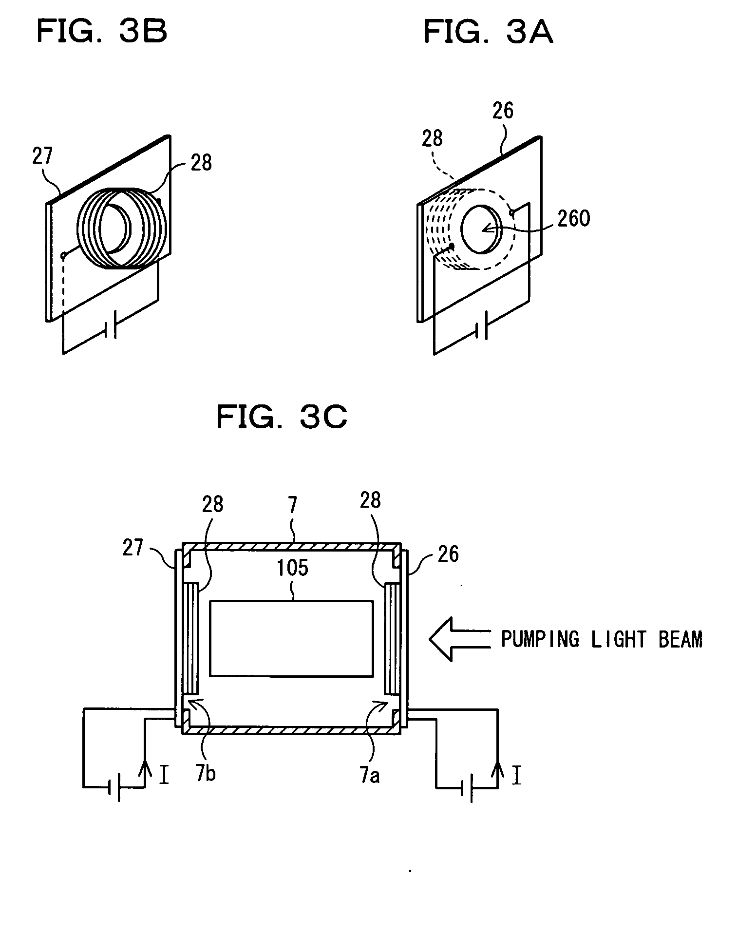
[0064]FIGS. 3A to 3C are diagrams showing a first embodiment of the present invention. As shown in FIGS. 3A to 3C, reference numerals 26 and 27 represent printed boards, 105 a resonance cell having atoms such as those of rubidium or cesium enclosed therein, 7 a cylindrical cavity resonator having the resonance cell 105 accommodated therein, respectively. The printed board (first printed board) 26 has provided an aperture (light beam passing aperture) 260 capable of leading a pumping light beam into the resonance cell 105 having the above atoms enclosed therein. As shown in FIG. 3B, the printed board (second printed board) 27 has an optical detector such as a PD (not shown) mounted thereon for monitoring the aforesaid pumping light beam. Further, both of the printed boards 26 and 27 have first and second coils (solenoid coils) 28 mounted thereon as magnetic field generating means, respectively, so that the first and second coils do not block the pas...

second embodiment

[C] Description of Second Embodiment

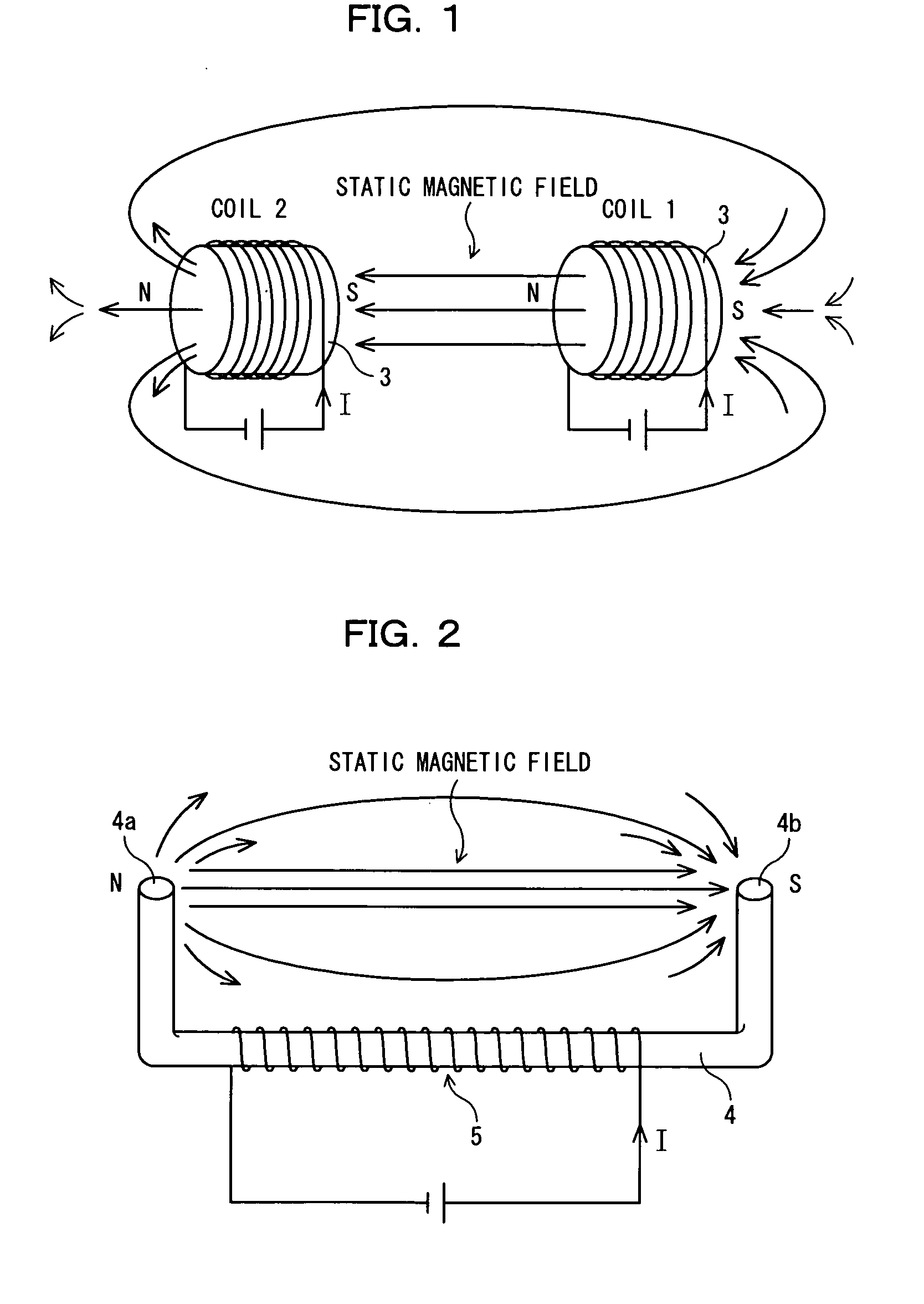
[0084]FIG. 8 is a set of diagrams each showing a second embodiment of the present invention. Of these diagrams, FIG. 8A is a schematic perspective view showing interlayer patterns 41, 42 and 43 of a multilayer (three layers) printed board 40. FIG. 8B is a schematic perspective view showing a construction realizing a static magnetic field generating circuit which is equivalent to one using the multilayer printed board 40 described with reference to FIG. 2. FIG. 8C is a schematic perspective view showing a construction provided with a resonance cell 105 in a static magnetic field created by the static magnetic field generating circuit shown in FIG. 8B.

[0085] As shown in FIG. 8A, an interlayer pattern 42 serving as an intermediate layer of the multilayer printed board 40 is composed of a straight conductive pattern (hereinafter referred to as straight pattern) 421 formed of a microstrip line (or strip line) and via holes 422 provided on both the sid...


PUM


Abstract

The present invention relates to a static magnetic field applying structure for use in an atomic oscillator in which plural sets of magnetic field generating means are provided with spacing interposed among them, and a resonance cell is disposed in a space between the magnetic field generating means. The object of the present invention is to realize the static magnetic field applying structure which can be small-sized and produced at a low cost.

Description

BACKGROUND OF THE INVENTION [0001] (1) Field of the Invention [0002] The present invention relates to a static magnetic filed applying structure for use in an atomic oscillator. In particular, the present invention relates to a structure for applying a static magnetic filed for use in an atomic oscillator of a passive-type based on a principle of optical pumping. [0003] (2) Description of Related Art [0004] Recently, the information communication network tends to move forward to a digital network construction, and with this tendency, it becomes indispensable to prepare a clock source which can provide a highly accurate and highly stable clock. A rubidium atom oscillator is drawing attention as the clock source, and it is requested to establish a way of small-sizing and low-cost production. In particular, the recent request is to establish a way of fabricating the oscillator having a thin body from a device-mounting standpoint. [0005] How the atomic oscillator is made into a thin bod...

Claims


Application Information

Patent Timeline
Patent Type & Authority Applications(United States)
IPC IPC(8): H03B9/10H03L7/26H01S1/06
CPCH01S1/06
Inventor MATSUURA, HIDEYUKIKIKUCHI, AKIRAATSUMI, KEN
Owner FUJITSU LTD
Why Eureka
Try Eureka