

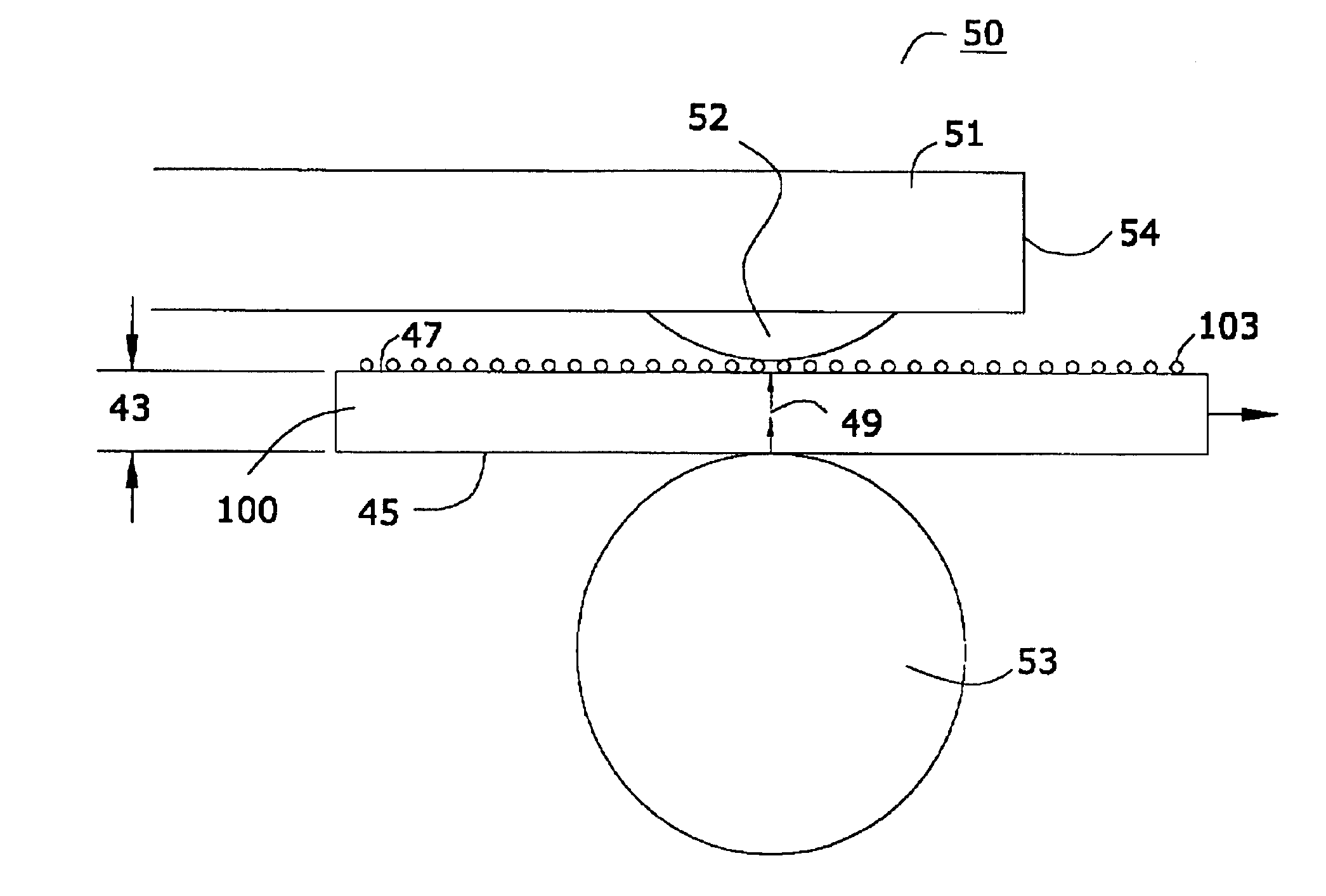
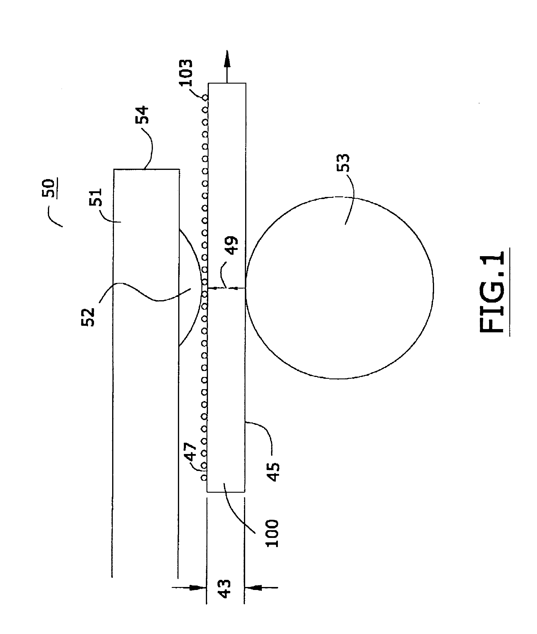
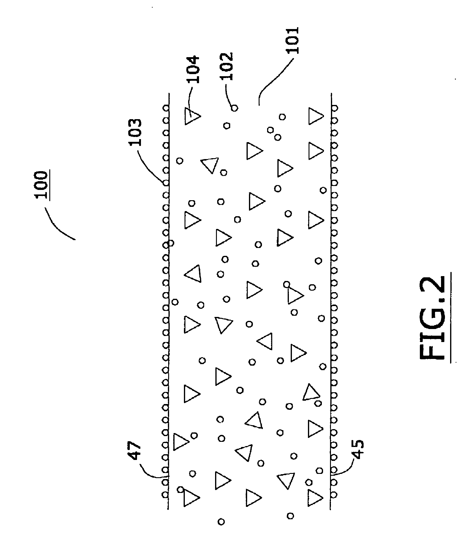
Thermal printing and cleaning assembly
a technology of thermal printing and cleaning assembly, which is applied in the direction of printing, ink ribbons, inking apparatus, etc., can solve the problems of degrading print quality, affecting the use of thermal printing heads, and accumulating contaminates on the print heads
- Summary
- Abstract
- Description
- Claims
- Application Information
AI Technical Summary
Benefits of technology
Problems solved by technology
Method used
Image

Examples
example 1
[0110] An I10 thermal transfer ribbon (available from International Imaging Materials, Inc., 310 Commerce Dr., Amherst, N.Y., 14228) was used to print lines of 0, 37, and 80 duty cycle onto a paper receiving sheet using a Zebra 140Xill thermal transfer printer (available from Zebra Technologies Corporation LLC, 333. Corporate Woods Parkway, Vernon Hills, Ill., 60061). As used herein, the term duty cycle refers to the percentage of the time that the print head elements are energize and thus cause thermal transfer.
[0111] The printer was operated at a printing speed of 8 inches per second and a darkness setting of 17. Two full ribbons, each 300 meters in length, were printed. The thermal print head was removed from the printer and examined under an optical microscope with a magnification of 50×. Microscopic examination of the array of print head heating elements revealed that, in the section of the array where the 37 and 80% duty cycle lines were printed, a build-up of blackish contam...
example 2
[0113] A 12 inch long and 4 inch wide sheet of a Sato printhead cleaning card with a Sheffield smoothness of 100 (obtained from the Sato Company as the “Sato Thermal Printer Cleaning Sheet”) was placed in the printing nip of the Zebra printer; this cleaning sheet was found to comprise particulate alumina.
[0114] The Sato cleaning sheet was completely pulled through the printing nip by hand at a speed of about 4 inches per second. The print head was removed from the printer, and the array of print head heating elements were examined with an optical microscope. The microscopic analysis revealed that the cleaning action of the Sato cleaning card removed a significant portion of the contamination built up on the portions of the array of print head heating elements where the 80 and 37 percent duty cycle lines were printed. In addition, the microscopic examination revealed that the array of print head heating elements was severely scratched by the action of the Sato cleaning card. It was ...
example 3
[0115] In substantial accordance with the procedure described in Example 1, a cleaning assembly was made in accordance with the procedure of such example and was evaluated. In this experiment, no thermal transfer ribbon was actually printed, but 400 meters of the synthetic paper cleaning assembly of Example 1 was pulled past and through the nip of the printer. By comparison, in Example 2 only about 12 inches of the Sato cleaning sheet was actually contacted with the print head.
[0116] Despite an exposure which was at least 120 times as great to the cleaning assembly of Example 2, inspection of the print head revealed no scratching or damage to the array of print head heating elements. The print head was reinstalled in the printer and found to be completely operational with no deterioration of performance (when compared to the performance of the print head before the 400 meters of synthetic paper cleaning assembly was pulled through the printer nip).
PUM
 Abstract
Description
Claims
Application Information