Extruder for welding plastic components

a technology of extruder and plastic components, which is applied in the field of extruder for welding plastic components, can solve the problems of not being free from drawbacks and aspects that can be improved, not being able to achieve the optimal flow of additional welding material, and being known

Inactive Publication Date: 2005-06-16
RITMO SRL
View PDF7 Cites 12 Cited by
  • Summary
  • Abstract
  • Description
  • Claims
  • Application Information

AI Technical Summary

Benefits of technology

[0015] The aim of the present invention is to provide an extruder for...

Problems solved by technology

The known extruders described here, although being known and used extensively on the market, are not free from drawbacks and aspects that can be improved.
A first drawback is that said cutting elements arranged at the end of the rear part do not provide uniform filament pieces, and this causes a less than optimum flow of additional welding material, since said material is not melted correctly.
A second drawback is linked to the fact that the rotating components, i.e., the screw feeder and the worm screw, must have a very precise axial tolerance, since any friction would da...

Method used


Image

  • Extruder for welding plastic components
  • Extruder for welding plastic components
  • Extruder for welding plastic components

Examples


Embodiment Construction

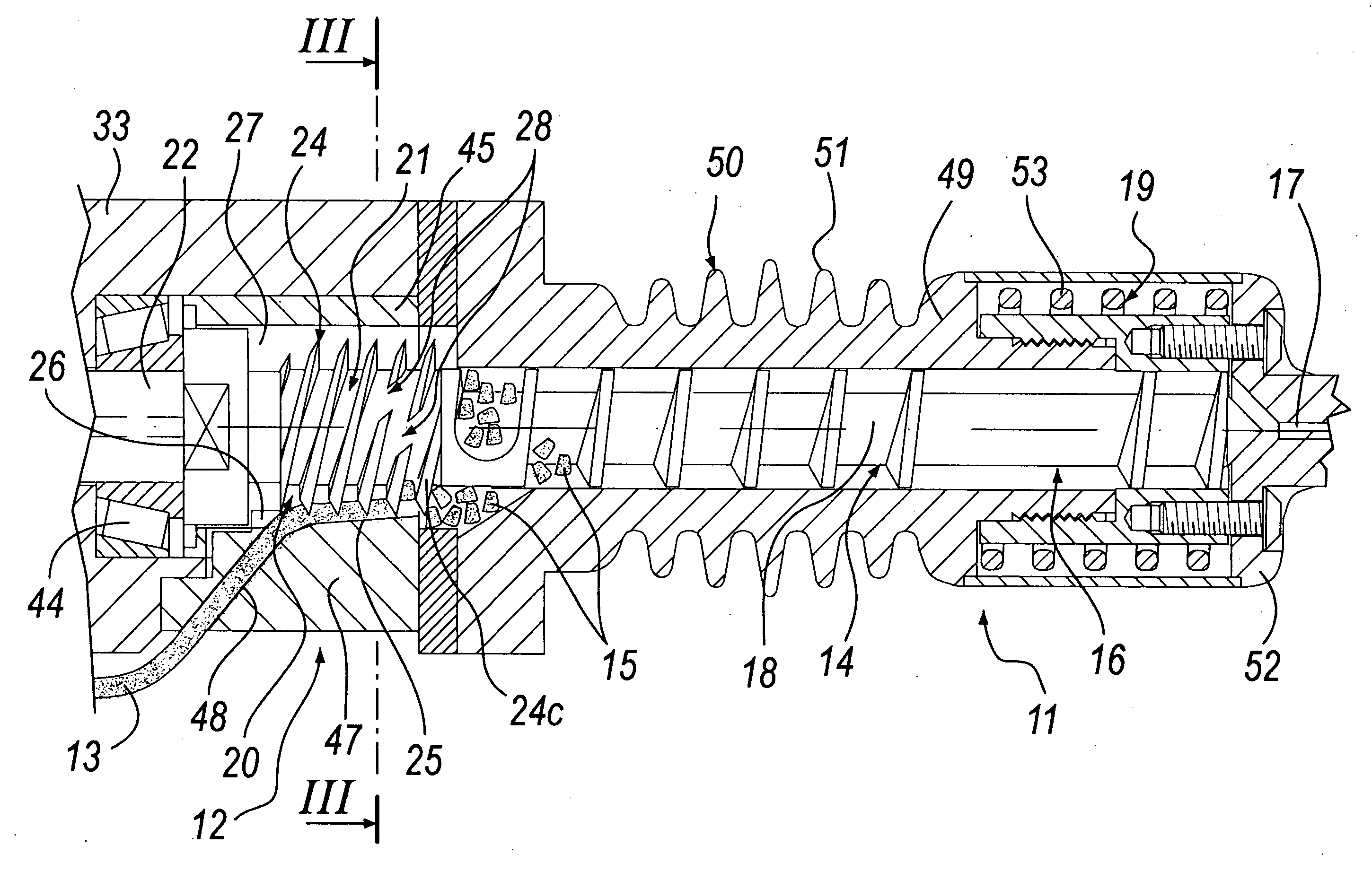
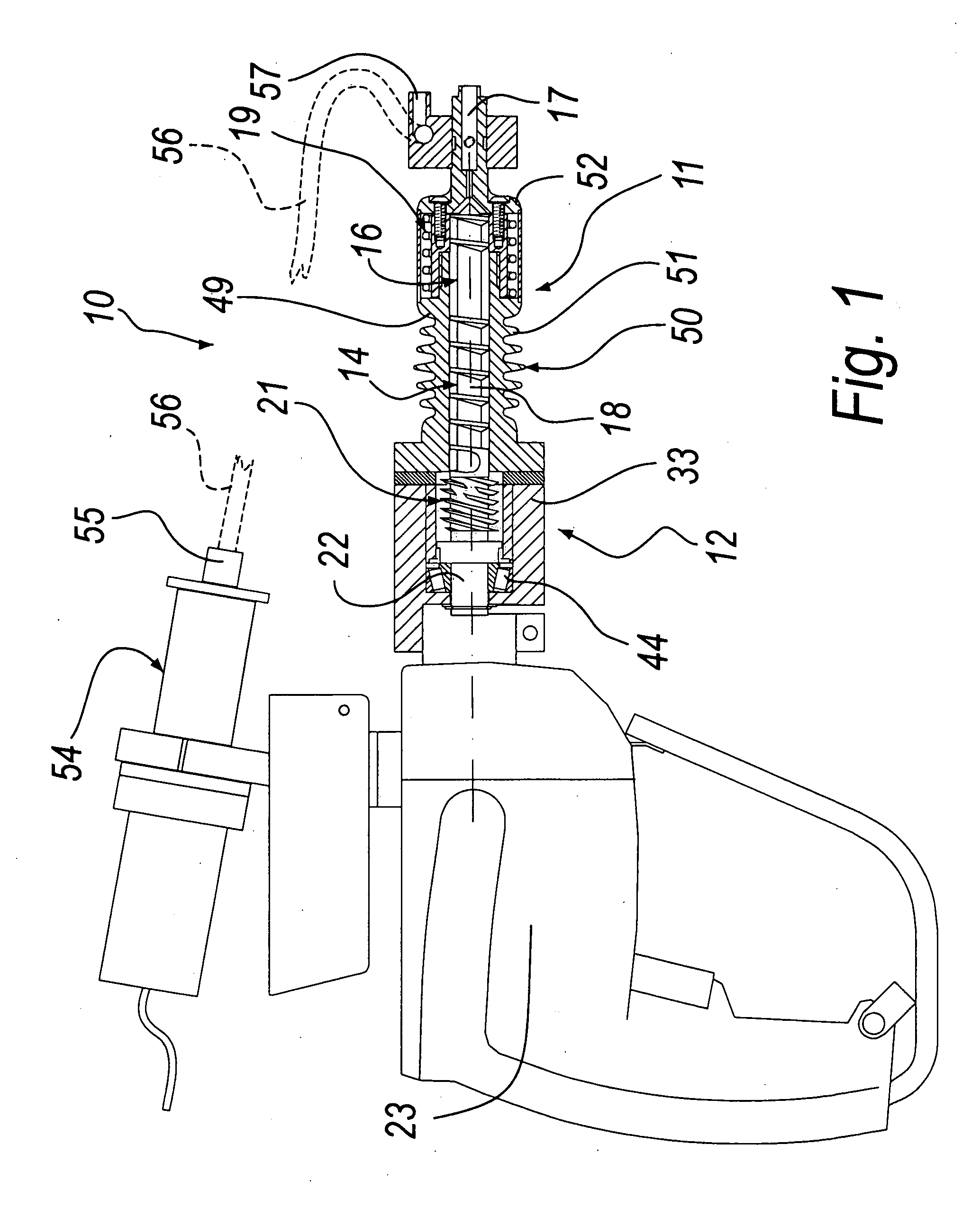
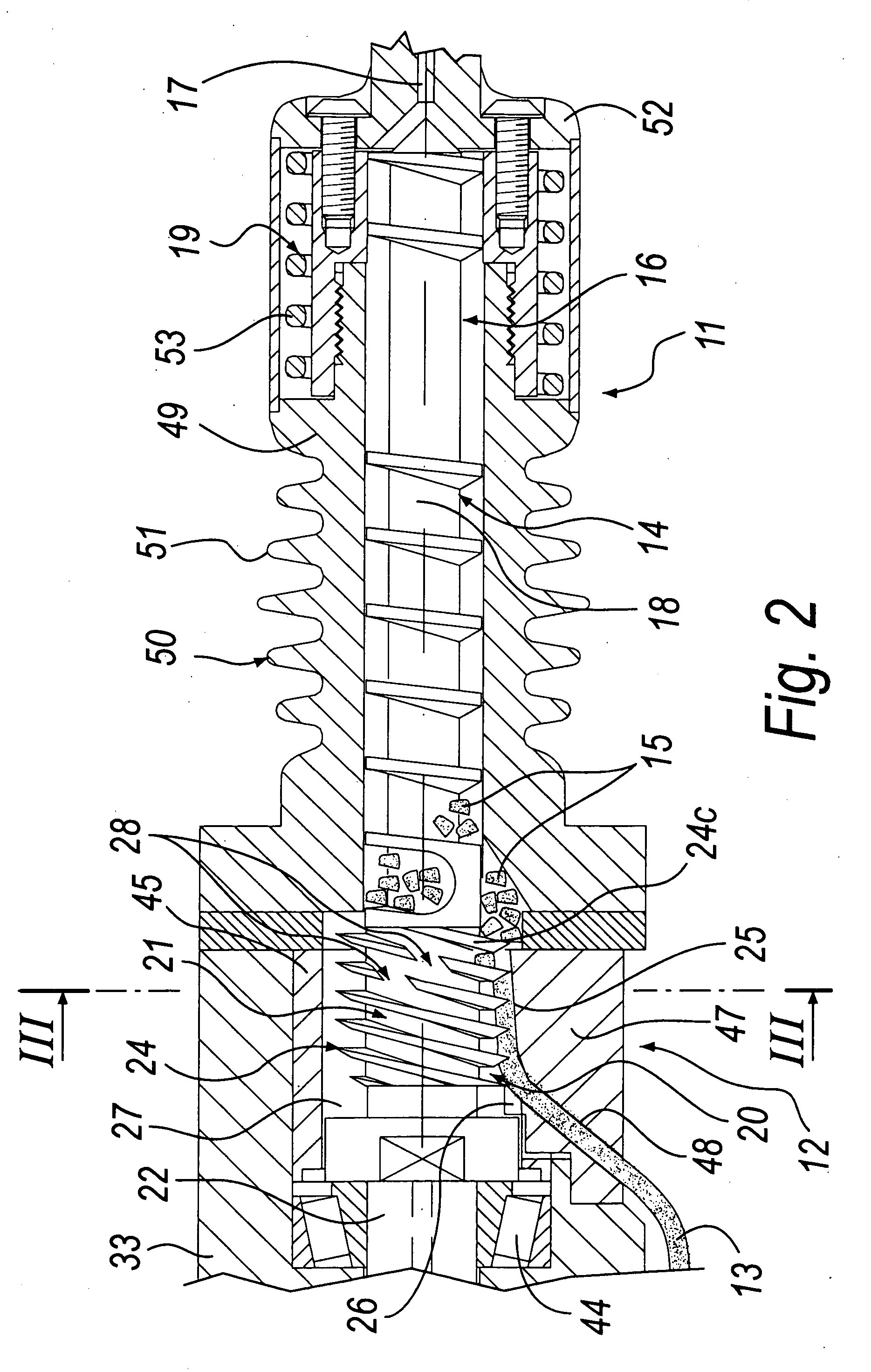
[0025] With reference to the figures, an extruder for welding plastic components according to the invention is generally designated by the reference numeral 10.

[0026] The extruder 10 comprises a front part 11, for plasticizing and ejecting plastic material to be added to the weld, and a rear part 12, for feeding and breaking up a continuous filament, here designated by the reference numeral 13, made of the plastic material of the additional welding material.

[0027] The front part 11 comprises a chamber 14 for transferring small pieces of plastic filament, generally designated by the reference numeral 15, from the rear part 12 to a melting chamber 16 that is located proximate to an ejection duct 17.

[0028] The transfer chamber 14 is substantially cylindrical and comprises internally a screw feeder 18, which moves the small filament pieces 15 toward the melting chamber 16 and the ejection duct 17.

[0029] The melting chamber 16 comprises electric resistor means 19, which will be descr...


PUM

PropertyMeasurementUnit
Diameteraaaaaaaaaa

Abstract

An extruder for welding plastic components, comprising a front part for plasticizing and ejecting additional plastic welding material, and a rear part, for feeding and breaking up a continuous filament made of the additional plastic material. The rear part comprises a feed channel that cooperates with a worm screw for the advancement of the filament. The feed channel is delimited by the thread of the worm screw on one side and by a sliding surface for the filament on the opposite side. The distance between the sliding surface and the crest of the thread decreases in the direction in which the filament is fed, in order to provide scoring of increasing depth on the filament. The thread comprises at least one discontinuity of the worm that has a sharp discontinuity end for cropping the filament at the scoring.

Description

BACKGROUND OF THE INVENTION [0001] Various methods are known for welding plastic components, such as for example containment tanks and other types of special article. [0002] One of the most widely used methods is welding with added material and is performed by means of an extruder composed of a front part, for plasticizing and ejecting plastic material to be added to the weld, and by a rear part for feeding and breaking up a continuous filament made of the additional material. [0003] The front part, for plasticizing and ejection, generally comprises a plasticizing chamber, inside which the small pieces of plastic filament that originate from the rear part are melted and moved by means of a screw feeder toward an ejection nozzle. [0004] Electric resistors for heating and melting the small pieces of filament are arranged around the plasticizing chamber. [0005] The rear part generally comprises a cylindrical feed chamber, in which a worm screw is arranged coaxially. [0006] A feed chann...

Claims


Application Information

Patent Timeline
IPC IPC(8): B05C17/005B29C48/395B29C48/52
CPCB29C47/0002B29C66/861B29C47/1054B29C65/40B29C47/585B29C47/6031B29C47/6093B29C47/807B29C47/822B29C47/827B29C47/8805B29C47/1018B29C47/6012B29C47/6025B29C66/0242B29C47/0014B29C48/875B29C48/02B29C48/05B29C48/287B29C48/2888B29C48/501B29C48/52B29C48/535B29C48/54B29C48/63B29C48/832B29C48/91
Inventor BORTOLI, RENZO
Owner RITMO SRL
Why Eureka
Try Eureka