

Automotive driveline components manufactured of hydrogenated nitrile butadiene rubber material
a technology of hydrogenated nitrile butadiene and driveline components, which is applied in the direction of couplings, other chemical processes, domestic articles, etc., can solve the problems of increasing stiffness in the boot, and achieve the effect of increasing the stiffness of the boot and constant operating temperatures
- Summary
- Abstract
- Description
- Claims
- Application Information
AI Technical Summary
Benefits of technology
Problems solved by technology
Method used
Image

Examples
Embodiment Construction
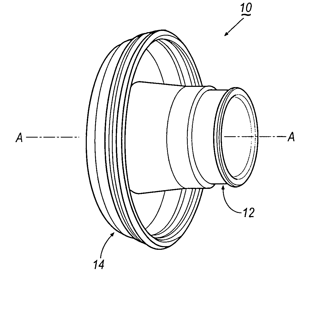
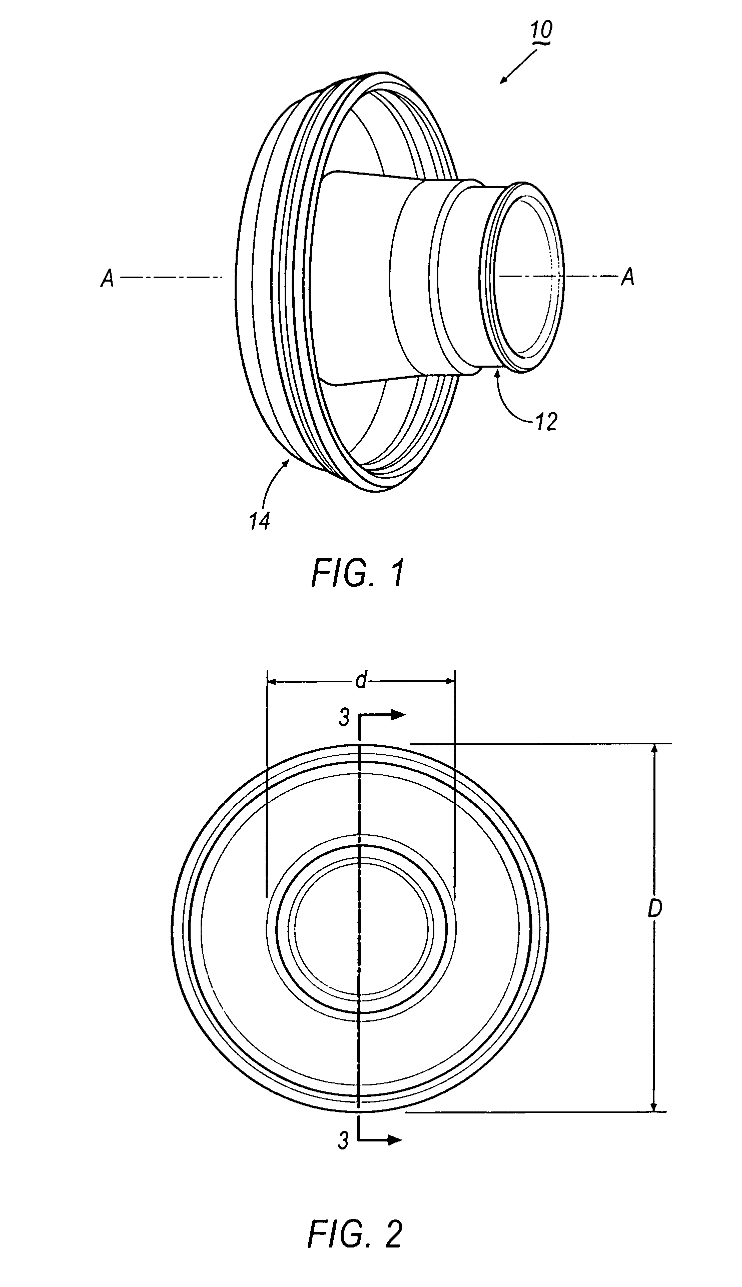
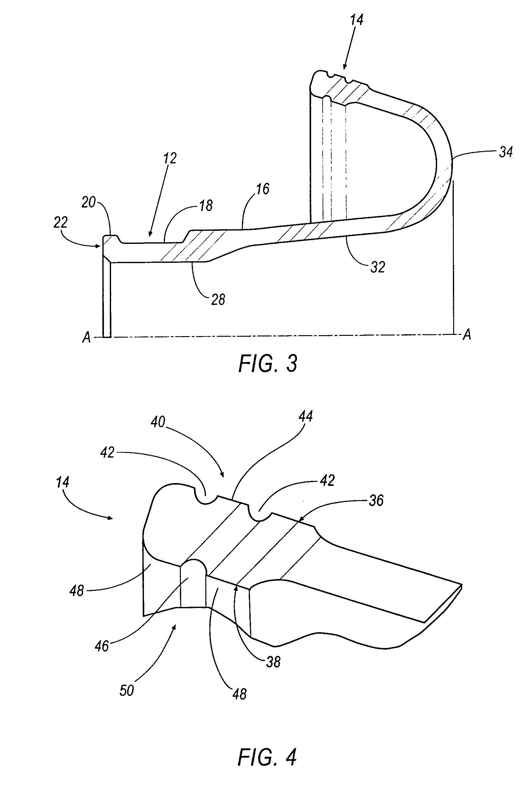
[0013] Referring to FIGS. 1-6, an embodiment of a flexible boot assembly, indicated generally at 10, for use with a constant velocity joint, is shown. Boot assembly 10 includes a first sealing end portion 12, and a second sealing end portion 14. First sealing end portion 12 has a first outer diameter d that is less than an outer diameter D of second sealing end portion 14. Both first and second sealing end portions 12, 14 are positioned around a common axis A.
[0014] An outside surface 16 of first end portion 12 includes an annular groove 18 formed therearound. An annular ridge 20 extends around a distal end 22 of first sealing end portion 12, adjacent to annular groove 18. Annular ridge 20 defines an inwardly sloping first flange 24. A second flange 26 is positioned opposite first flange 24. Second flange 26 also slopes inwardly toward annular groove 18 from the outside surface 16.
[0015] First end portion 12 also includes an inner contact surface 28. Inner contact surface 28 may b...
PUM
| Property | Measurement | Unit |
|---|---|---|
| diameter | aaaaa | aaaaa |
| length | aaaaa | aaaaa |
| elongation | aaaaa | aaaaa |
Abstract
Description
Claims
Application Information