Wireless lan system, communication terminal and communication program

Inactive Publication Date: 2005-06-16
BROTHER KOGYO KK
View PDF3 Cites 44 Cited by
  • Summary
  • Abstract
  • Description
  • Claims
  • Application Information

AI Technical Summary

Benefits of technology

[0016] The present invention is advantageous in that the load of the ta

Problems solved by technology

However, with wireless stations equipped with a user interface of lower operability compared to that of a PC (e.g. printers providing services via a network), adjusting the settings through the user interface becomes an extremely complex and troublesome task.
However, even the remote setup described above is still a troublesome task to the user since the user is required to move the wireless stations (after switching the communication method to the “ad hoc mode”) to positions allowing wireless communication or to move the PC to a position allowing the direct connection to the wireless station by a cable.
Especially when a wireless station which has been used in the “infrastructure mode” is employed for the remote setup, the user has to return the communication method of the wireless station from the “ad hoc

Method used


Image

  • Wireless lan system, communication terminal and communication program
  • Wireless lan system, communication terminal and communication program
  • Wireless lan system, communication terminal and communication program

Examples


Example

Embodiment 1

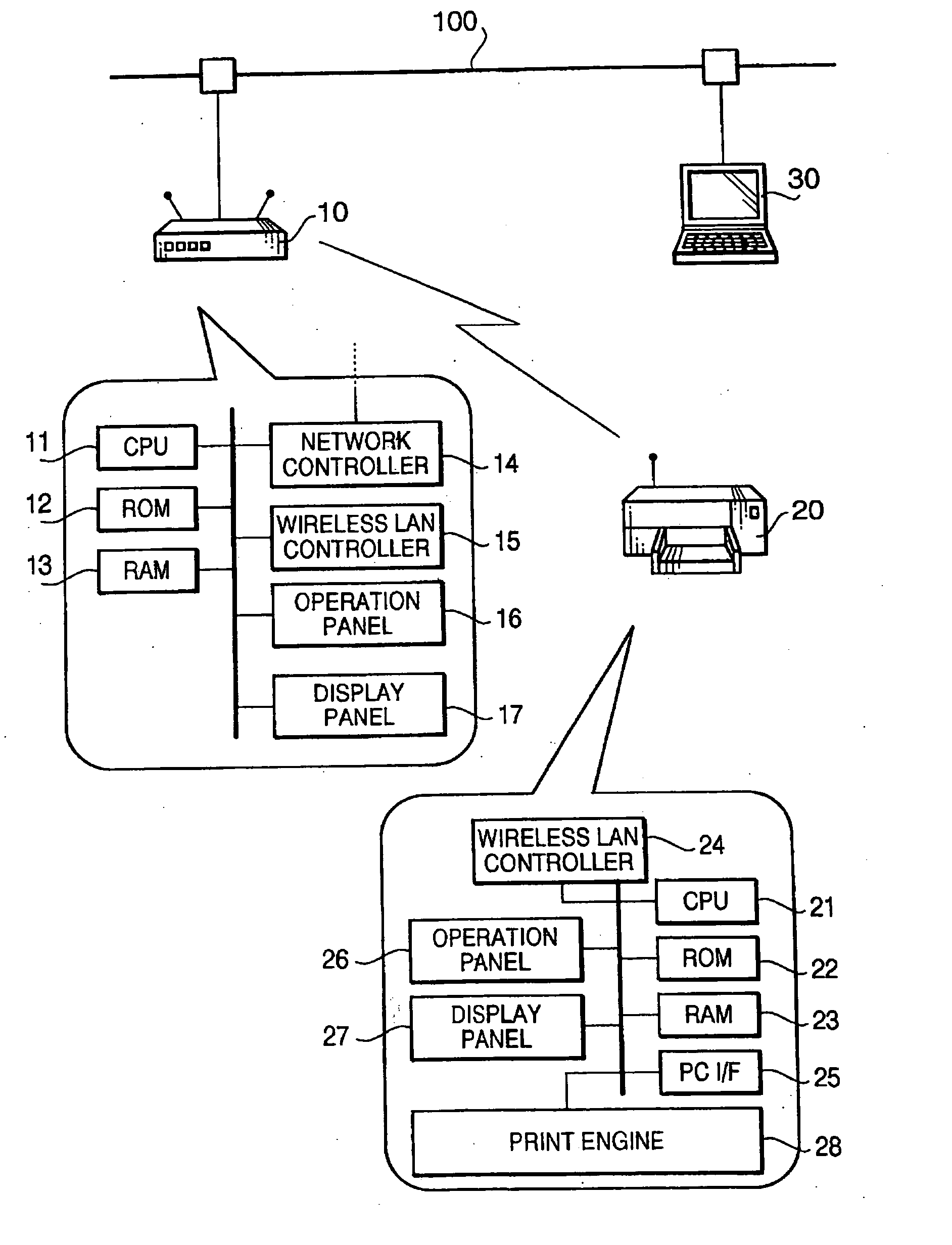
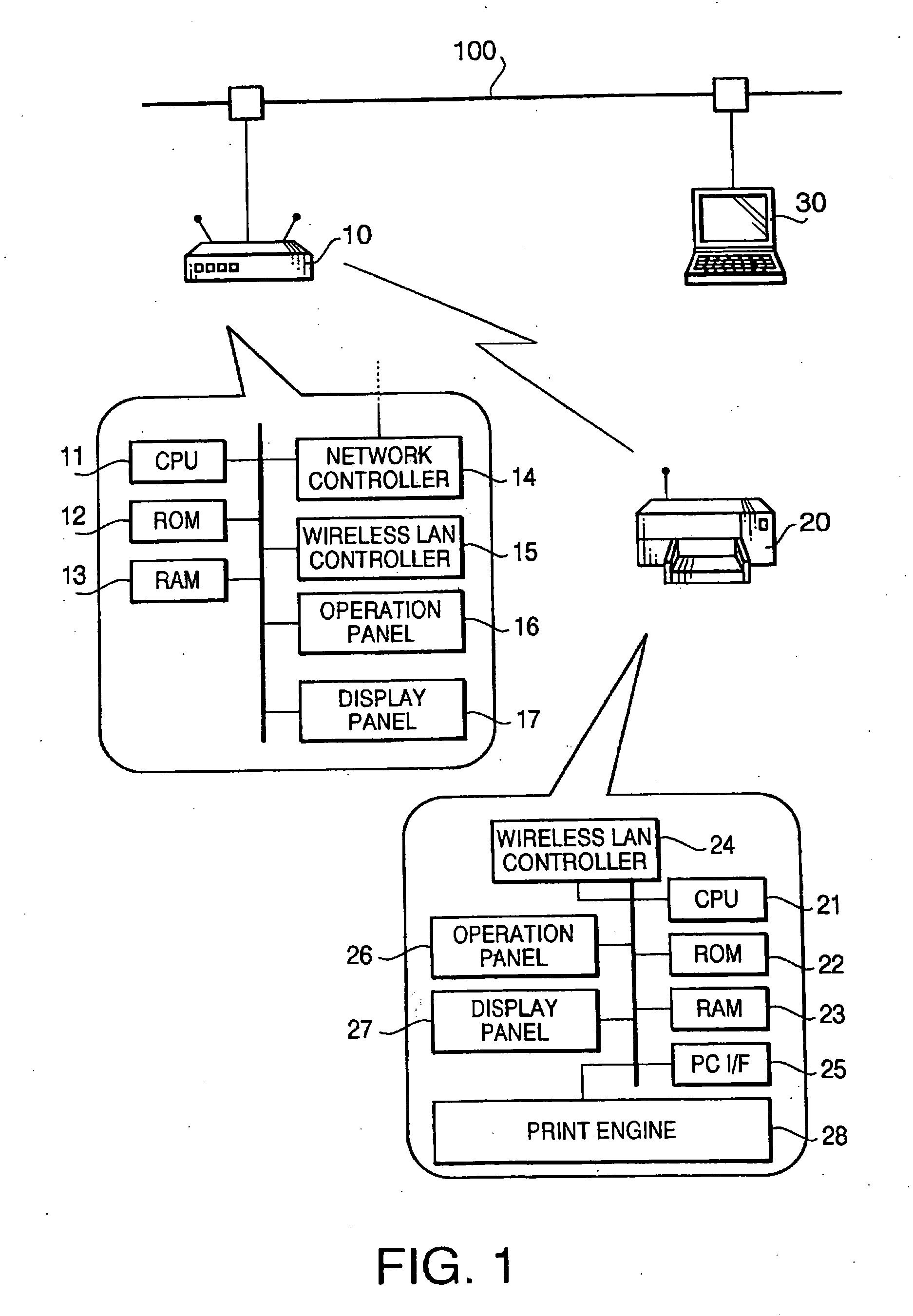
[0344]FIG. 1 shows an exemplary configuration of a wireless LAN system according to the present invention. It should be noted that a hardware configuration of the wireless LAN system is common among the embodiments and modifications described hereinafter, the wireless LAN system will be described once as a system according to the first embodiment.

[0345] The wireless LAN system shown in FIG. 1 is composed of an access point 10, a network printer 20 (hereinafter simply referred to as a “printer”), etc.

[0346] The access point 10, which is a wireless access point for relaying data communication between devices (or external networks) connected by cables 100 and data communication between wireless stations, includes a CPU 11, a RON 12, a RAM 13, a network controller 14, a wireless LAN controller 15, an operation panel 16, a display panel 17, etc.

[0347] The CPU 11 of the access point 10 controls the overall operation of the access point 10 by sending instructions to the com...

Example

[0409] The first embodiment can also be implemented with part of its composition altered to other composition as shown below. Incidentally, the composition shown below is also applicable to similar parts of other embodiments.

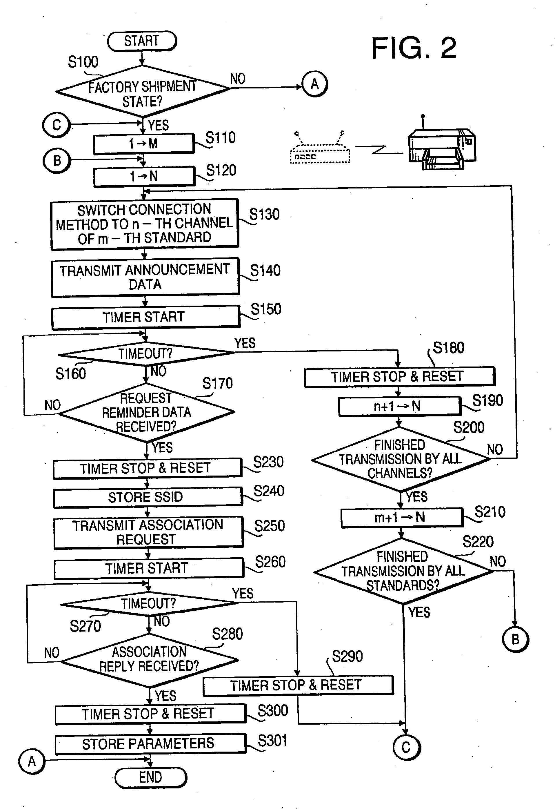
[0410] For example, while the process from the step S110 is executed only when the printer 20 is in its factory shipment state (S100 of FIG. 3), it is also possible to configure the printer 20 to execute the process from the step S110 even if it is not in the factory shipment state, in cases where the setting of the connection method is necessary (e.g. when part of the “parameters indicating the connection method” stored in the ROM 22 is lacking).

[0411] While the association request and association reply are exchanged after the exchange of the authentication request and authentication reply in the above embodiment, it is also possible to omit the authentication request / reply and carry out the exchange of the association request / reply only.

[0412] In the above ...

Example

[0418] A wireless LAN system in accordance with a second embodiment of the present invention is composed similarly to the system of the first embodiment except for some steps executed by the access point 10, therefore, only the point of difference will be explained below.

[0419]10>

[0420] In the following, a connection method instruction process which is conducted by the CPU 11 of the access point 10 will be described referring to FIG. 6. The connection method instruction process is configured by replacing part (sequence from the step S350) of the connection method instruction process in the first embodiment (FIG. 4) with the following procedure. In the following explanation, steps identical with those of the first embodiment will be referred to with the same step Nos. and detailed explanation thereof is omitted for brevity.

[0421] If the announcement data has not been registered yet in the step S350 (S350: NO), parameters specified by the announcement data are registered (e.g. regis...


PUM


Abstract

A wireless LAN system in which data communication between a wireless station whose connection method as a method for wireless connection can be set to one of a plurality of connection methods and a wireless access point whose connection method has been preset to one of the connection methods is made possible by setting the connection method of the wireless station to a method identical with the connection method of the wireless access point.

Description

BACKGROUND OF THE INVENTION [0001] The present invention relates to a wireless LAN system in which data communication between a wireless access point and a wireless station is made possible by setting the connection method of the wireless station to a method identical with the connection method of the wireless access point, a communication terminal usable in the wireless LAN system, and a communication program. [0002] Nowadays, the so-called wireless LANS, realizing data communication among a plurality of wireless stations or data communication between a wireless station and an external network by use of radio waves, have become widespread. [0003] In the wireless LANs, various communication methods, such as “infrastructure mode” in which each wireless station carries out radio communication via a repeater station and “ad hoc mode” in which wireless stations directly communicate with each other by radio, are employed. Each wireless station, configured to be capable of switching its c...

Claims


Application Information

Patent Timeline
IPC IPC(8): G06F3/12H04L12/28H04L12/56H04L29/06
CPCG06F3/1203H04W88/06G06F3/1226G06F3/1236G06F3/1285G06F3/1292H04L63/0442H04L63/0823H04W12/02H04W12/06H04W28/18H04W76/02H04W84/12H04W84/18G06F3/1204H04W76/10H04W12/037H04W28/0215H04W60/04
Inventor MATSUDA, MAKOTOOHARA, KIYOTAKATAGAWA, NORIO
Owner BROTHER KOGYO KK
Why Eureka
Try Eureka