Bone plate with interference fit screw

a screw and bone plate technology, applied in the field of bone plate with interference screw, can solve the problems of reducing (setting) fracture, limiting the angle of screw installation, and limiting surgeons' current use of plates

Inactive Publication Date: 2005-06-16
ODRISCOLL SHAWN W +1
View PDF99 Cites 443 Cited by
  • Summary
  • Abstract
  • Description
  • Claims
  • Application Information

AI Technical Summary

Problems solved by technology

Second, the surgeon reduces (sets) the fracture.
However, a threaded aperture typically limits the angle of installation of the screw, since the threads provide a fixed orientation for engagement between the screw

Method used


Image

  • Bone plate with interference fit screw
  • Bone plate with interference fit screw
  • Bone plate with interference fit screw

Examples


Embodiment Construction

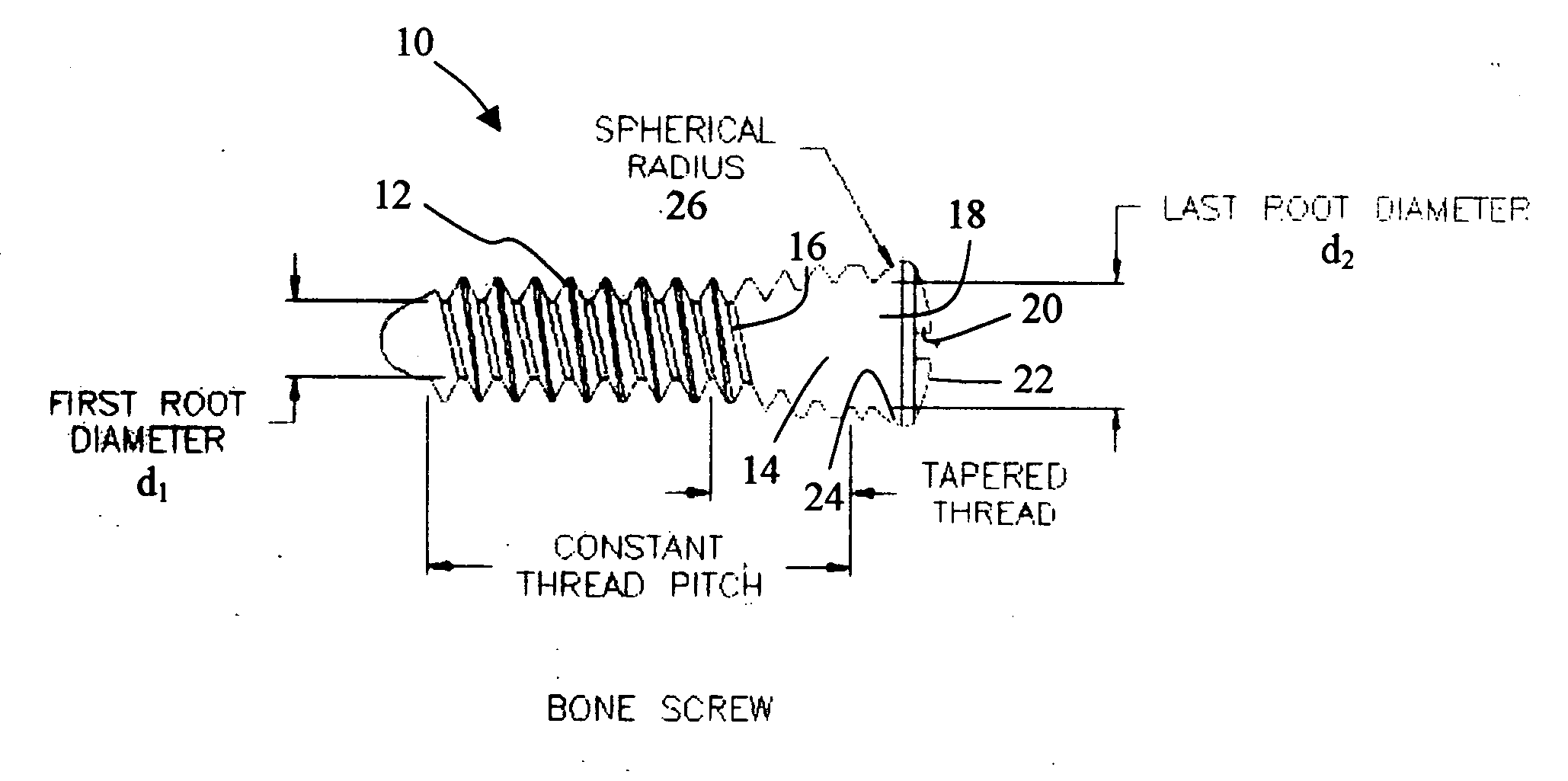
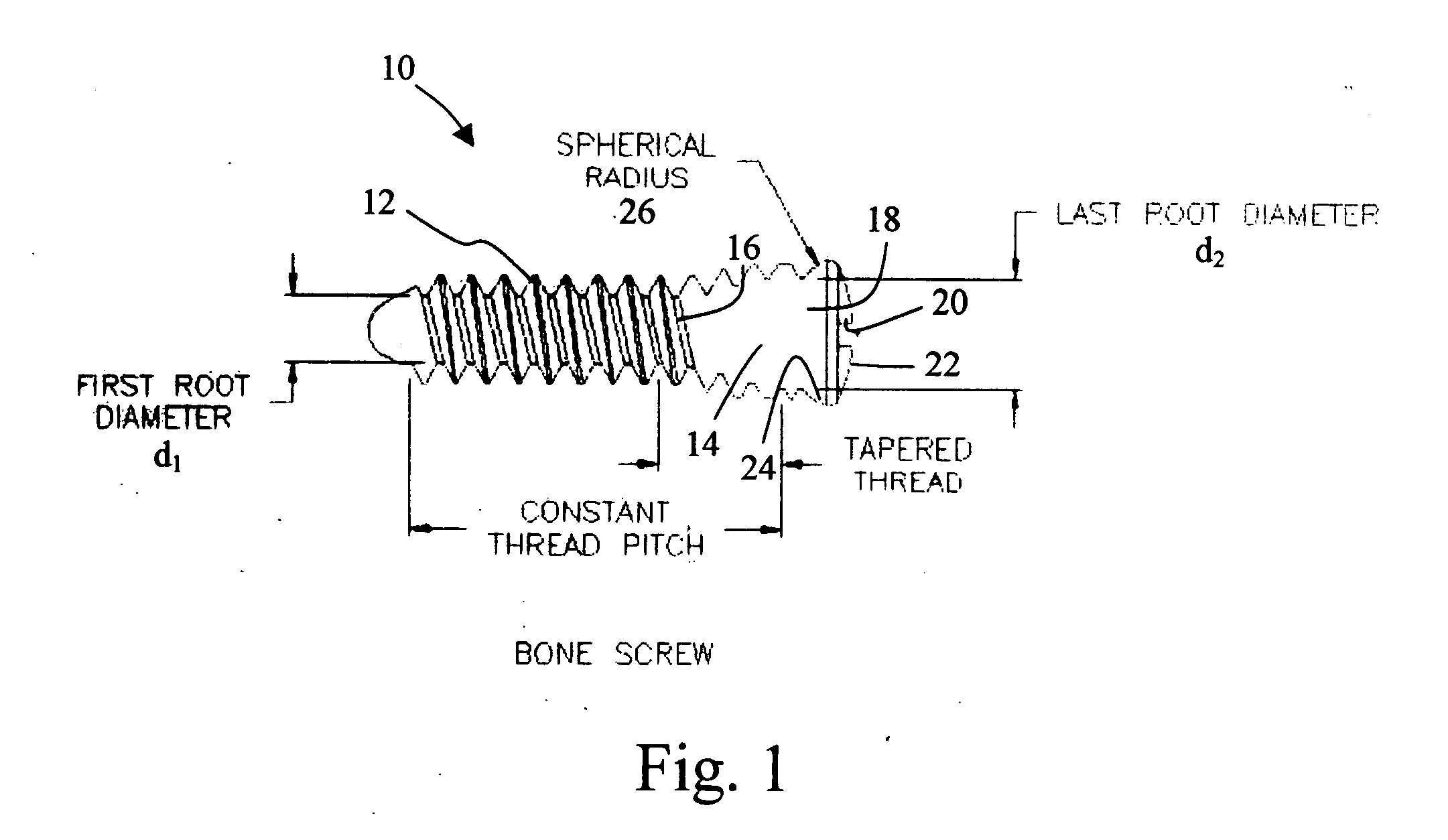
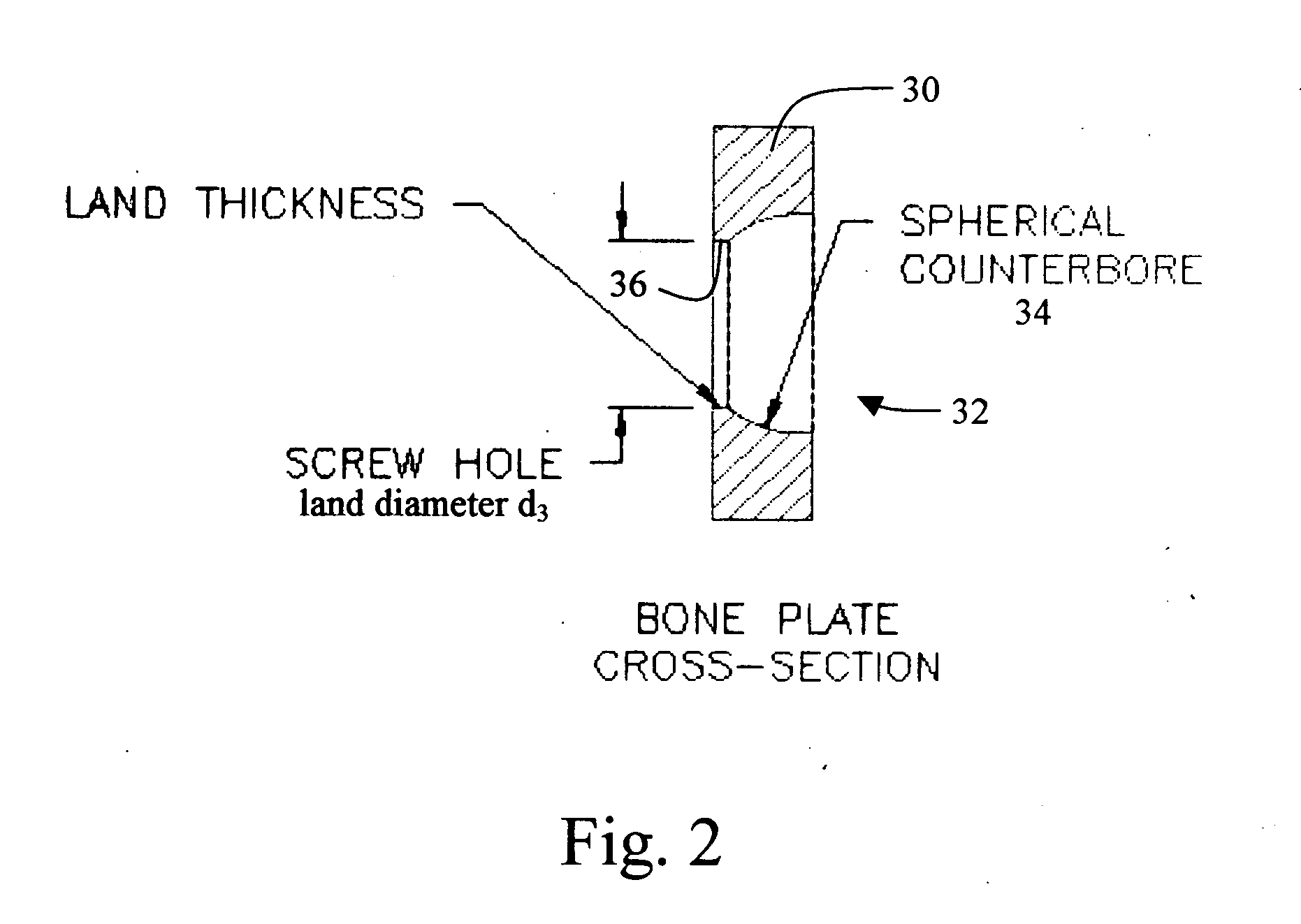
[0015] The present teachings provide systems, including apparatus and methods, for internal fixation of a fractured or otherwise compromised bone. These systems may include and / or make use of locking screws and / or bone plates, among others. The locking screws may lock into place at a fixed angle within an unthreaded aperture of the plate, for example, due to interference between one or more threads of the screw and an inner lip of the aperture. Thus, a locking screw may provide spaced engagement of an aperture to the underlying bone. Apertures of the plate also may be configured to accept non-locking, variable-angle screws that may be inserted through the apertures at variable angles to provide compressed engagement of the aperture to the bone. Thus, the systems may allow a surgeon to choose independently between compressed and spaced engagement for each aperture in the plate, by independently selecting a locking or a non-locking screw for each unthreaded aperture of the plate.

I. E...


PUM


Abstract

Systems, including apparatus and methods, for internal fixation of a fractured or otherwise compromised bone. These systems may include and/or make use of bone plates, locking screws, and/or kits, among others.

Description

CROSS-REFERENCES TO PRIORITY APPLICATIONS [0001] This application is based upon and claims the benefit under 35 U.S.C. § 119(e) of the following U.S. provisional patent application, which is incorporated herein by reference in its entirety for all purposes: Ser. No. 60 / 480,517, filed Jun. 20, 2003. CROSS-REFERENCES TO RELATED APPLICATIONS [0002] This application incorporates by reference in their entirety for all purposes the following patent applications: U.S. Provisional Patent Application Ser. No. 60 / 297,008, filed Jun. 8, 2001; PCT patent application Ser. No. PCT / US02 / 18623, filed Jun. 10, 2002; and U.S. patent application Ser. No. 10 / 731,173, filed Dec. 8, 2003. [0003] This application also incorporates by reference in their entirety for all purposes the following patent applications: U.S. Provisional Patent Application Ser. No. 60 / 498,807, filed Aug. 28, 2003; and U.S. Provisional Patent Application Ser. No. 60 / 498,870, filed Aug. 28, 2003.INTRODUCTION [0004] The human skeleto...

Claims


Application Information

Patent Timeline
IPC IPC(8): A61B17/56A61B17/80A61B17/86
CPCA61B17/8605A61B17/8052
Inventor O'DRISCOLL, SHAWN W.GILLARD, JOEL
Owner ODRISCOLL SHAWN W
Why Eureka
Try Eureka