Methods and devices for minimally invasive spinal fixation element placement

a spinal fixation element and minimally invasive technology, applied in the field of spinal surgery tools, can solve the problems of increasing patient trauma and recovery time, significant damage to surrounding tissue and muscle, undesired lengthening of surgical procedures,

Active Publication Date: 2005-06-16
DEPUY SYNTHES PROD INC
View PDF96 Cites 396 Cited by
  • Summary
  • Abstract
  • Description
  • Claims
  • Application Information

AI Technical Summary

Benefits of technology

[0011] Additional methods and devices for introducing a spinal fix

Problems solved by technology

While this procedure offers advantages over prior art invasive techniques, the transverse introduction of the rod can cause significant damage to surrounding ti

Method used


Image

  • Methods and devices for minimally invasive spinal fixation element placement
  • Methods and devices for minimally invasive spinal fixation element placement
  • Methods and devices for minimally invasive spinal fixation element placement

Examples


Embodiment Construction

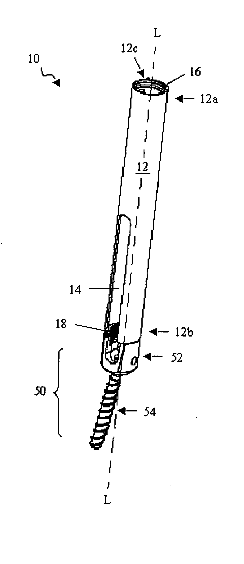
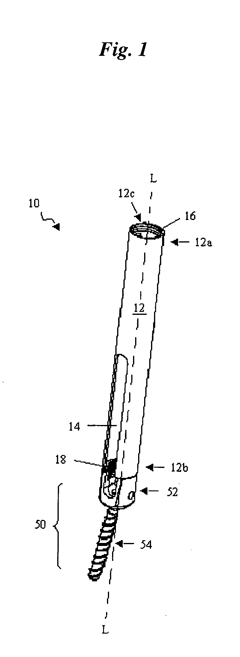
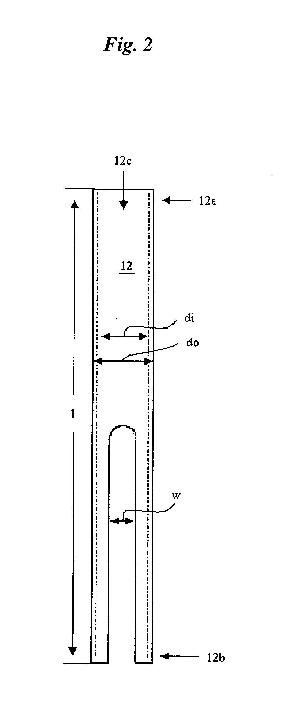
[0032] The present invention provides minimally invasive methods and devices for introducing a spinal fixation element into a surgical site in a patient's spinal column. In general, the method involves advancing a spinal fixation element in a lengthwise orientation along a minimally invasive pathway that extends from a minimally invasive percutaneous incision to a spinal anchor site. In an exemplary embodiment, a percutaneous access device is used to create the minimally invasive pathway for receiving the spinal fixation element and for delivering the fixation element to a spinal anchor site. The spinal fixation element is preferably inserted through a lumen in the percutaneous access device in a lengthwise orientation, such that the spinal fixation element is oriented substantially parallel to a longitudinal axis of the percutaneous access device. As the spinal fixation element approaches or reaches the distal end of the pathway, the spinal fixation element can be manipulated to or...


PUM


Abstract

Minimally invasive methods and devices for introducing a spinal fixation element into a surgical site in a patient's spinal column are provided. In general, the method involves advancing a spinal fixation element in a first, lengthwise orientation along a pathway extending from a minimally invasive percutaneous incision to a spinal anchor site. As the spinal fixation element approaches the spinal anchor site, the fixation element can be manipulated to extend in a second orientation, which is preferably substantially transverse to the first orientation, to position the fixation element in relation to one or more spinal anchors.

Description

FIELD OF THE INVENTION [0001] This application relates to tools for use in spinal surgery, and in particular to minimally invasive methods and devices for introducing a spinal fixation element to one or more spinal anchor sites within a patient's spine. BACKGROUND OF THE INVENTION [0002] For a number of known reasons, spinal fixation devices are used in orthopedic surgery to align and / or fix a desired relationship between adjacent vertebral bodies. Such devices typically include a spinal fixation element, such as a relatively rigid fixation rod, that is coupled to adjacent vertebrae by attaching the element to various anchoring devices, such as hooks, bolts, wires, or screws. The fixation elements can have a predetermined contour that has been designed according to the properties of the target implantation site, and once installed, the instrument holds the vertebrae in a desired spatial relationship, either until desired healing or spinal fusion has taken place, or for some longer p...

Claims


Application Information

Patent Timeline
IPC IPC(8): A61B17/00A61B17/70A61B17/88
CPCA61B17/00234A61B17/7011A61B17/7035A61B17/7074A61B17/7085Y10S606/914A61B17/7037
Inventor ANDERSON, DAVID GREGSICVOL, CHRISTOPHER W.ROSS, GEORGE JOSEPHSELOVER, SEAN P.
Owner DEPUY SYNTHES PROD INC
Why Eureka
Try Eureka