Chiropractic adjustor apparatus with rotation hub

Inactive Publication Date: 2005-06-16
ERCHONIA CORP
View PDF6 Cites 62 Cited by
  • Summary
  • Abstract
  • Description
  • Claims
  • Application Information

AI Technical Summary

Problems solved by technology

During operation, many of the prior art devices tend to rotate, or twist, out of the user's grip, as a result of the rotational components of the force exerted on the sh

Method used


Image

  • Chiropractic adjustor apparatus with rotation hub
  • Chiropractic adjustor apparatus with rotation hub
  • Chiropractic adjustor apparatus with rotation hub

Examples


Embodiment Construction

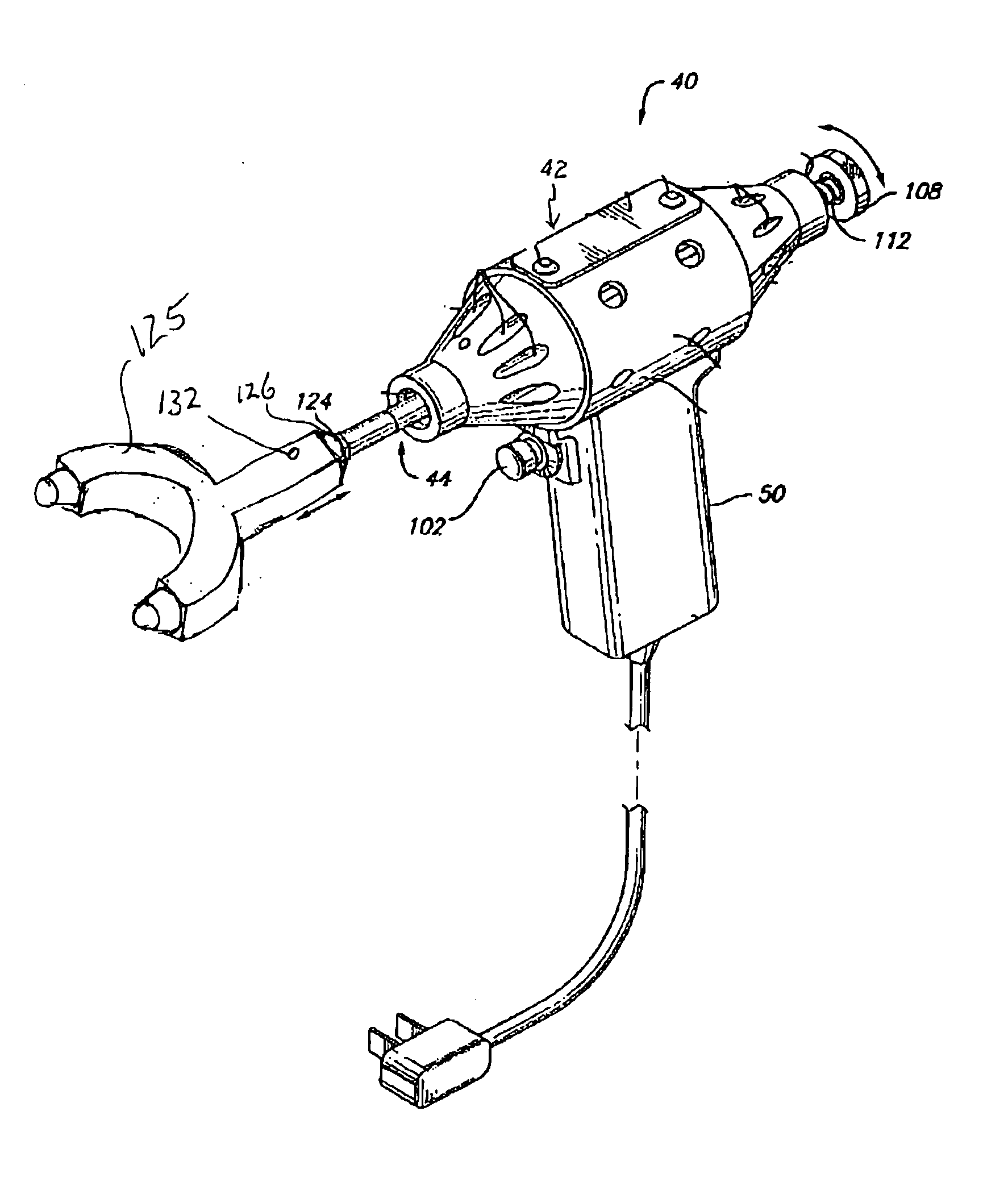
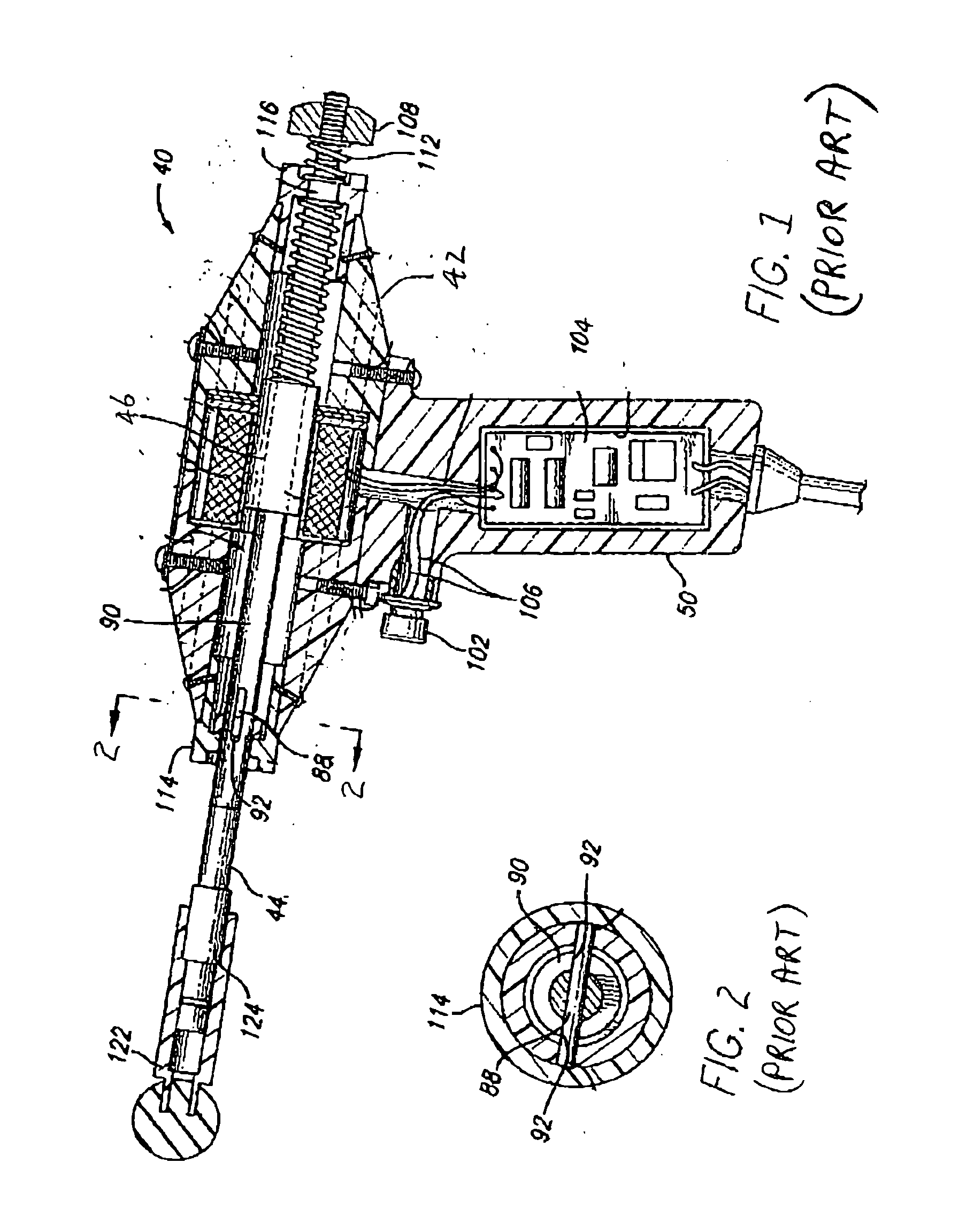
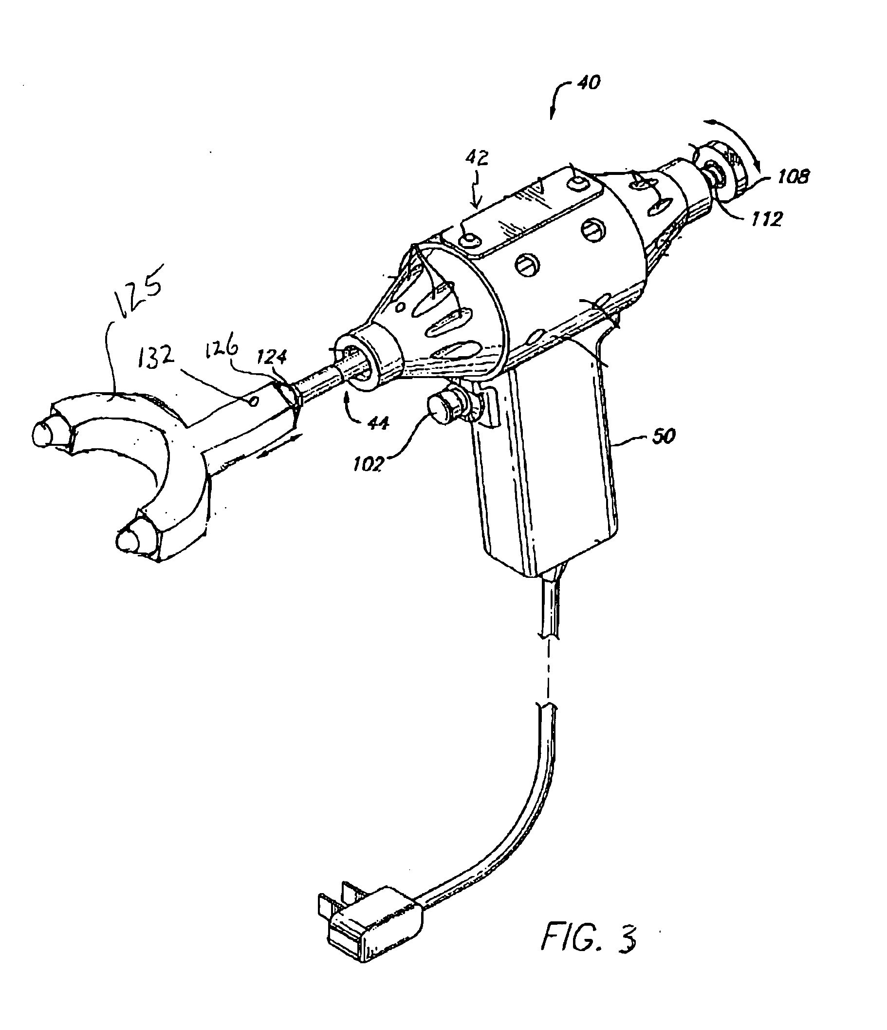
[0015] Referring to the drawings and particularly to FIG. 1 and FIG. 2, there is illustrated a chiropractic adjustor apparatus of the prior art, generally designated 40. The apparatus 40 basically includes a housing 42 with a handle 50. An electromagnetic drive mechanism 46 located within the housing 42 is actuated by a trigger 102 that is electrically connected to an electronic control module 104 and hence to electromagnetic drive mechanism 46 by wires 106. Depression of the trigger 102 actuates the drive mechanism 46 to cause repetitive reciprocal vibratory movement of the shaft 44 relative to the housing 42.

[0016] A pin 88 is mounted through the forward portion of the shaft 44 in a transverse relationship thereto. A sleeve 90 extends about and along the forward portion of the shaft 44 and has a longitudinal slot 92 receiving each end of the pin 88 such that the shaft 44 can undergo longitudinal movement through the sleeve 90 relative to the housing 42 but cannot undergo rotation...


PUM


Abstract

A force-transmitting head for a chiropractic adjustor apparatus includes a hub which is rotatable in a cavity formed in the head and non-rotatably attached to a reciprocating shaft of the apparatus. A rotation pin extends through the body into the cavity and engages a track formed in the hub. Reciprocating movement of the shaft and hub causes a rotational movement of the body with passage of the rotation pin along the track. Also, a chiropractic adjustor apparatus incorporating the force-transmitting head.

Description

CROSS-REFERENCE TO RELATED APPLICATIONS [0001] This application claims the benefit of co-pending U.S. application Ser. No. 10 / 174,622 filed Jun. 19, 2002, which in turn claims the benefit of U.S. application Ser. No. 09 / 749,023 filed Dec. 26, 2000 and now issued as U.S. Pat. No. 6,537,236.FIELD OF THE INVENTION [0002] The present invention generally relates to a rotation hub for a chiropractic adjustor apparatus used to apply vibratory energy or force to a patient. More particularly, the invention relates to a chiropractic adjustor apparatus that allows limited, controlled rotation of a force-transmitting head during use. BACKGROUND OF THE INVENTION [0003] Chiropractic adjustments of the spinal vertebrae of a body involve the application of pressure or force in a known manner directly to the body by the hands of a chiropractor or by a chiropractic adjustor apparatus. Examples of such chiropractic adjustor apparatuses found in the prior patent art are those disclosed in U.S. Pat. No....

Claims


Application Information

Patent Timeline
IPC IPC(8): A61H1/00
CPCA61H1/008
Inventor TUCEK, KEVIN B.SHANKS, STEVEN C.
Owner ERCHONIA CORP
Why Eureka
Try Eureka