Diagnostics of impulse piping in an industrial process

Active Publication Date: 2005-06-23
ROSEMOUNT INC
View PDF99 Cites 121 Cited by
  • Summary
  • Abstract
  • Description
  • Claims
  • Application Information

AI Technical Summary

Problems solved by technology

Flow around the discontinuity causes both a pressure drop and increased turbulence.
Impulse lines can become plugged over time, which also adversely affects

Method used


Image

  • Diagnostics of impulse piping in an industrial process
  • Diagnostics of impulse piping in an industrial process
  • Diagnostics of impulse piping in an industrial process

Examples


Embodiment Construction

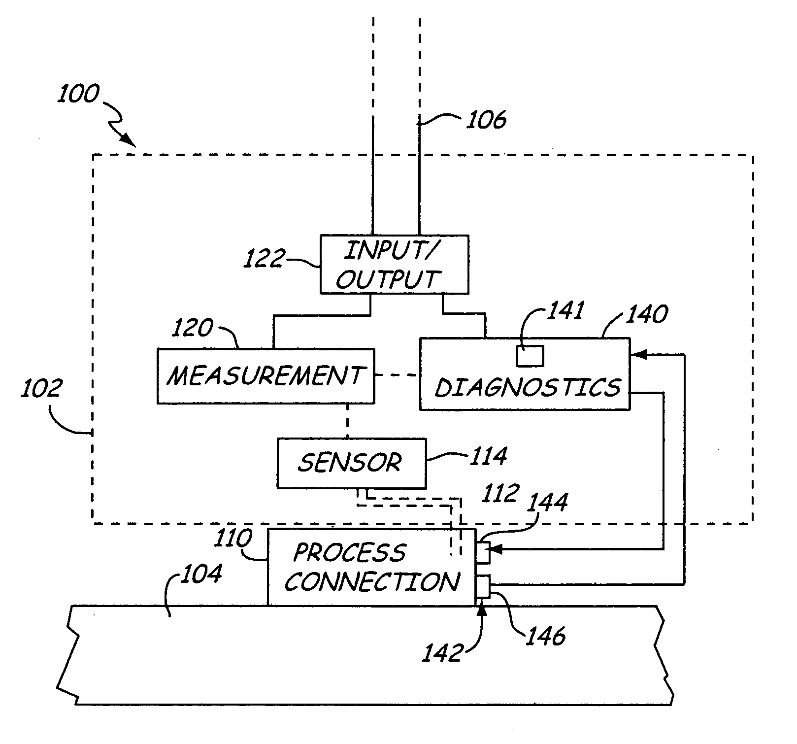
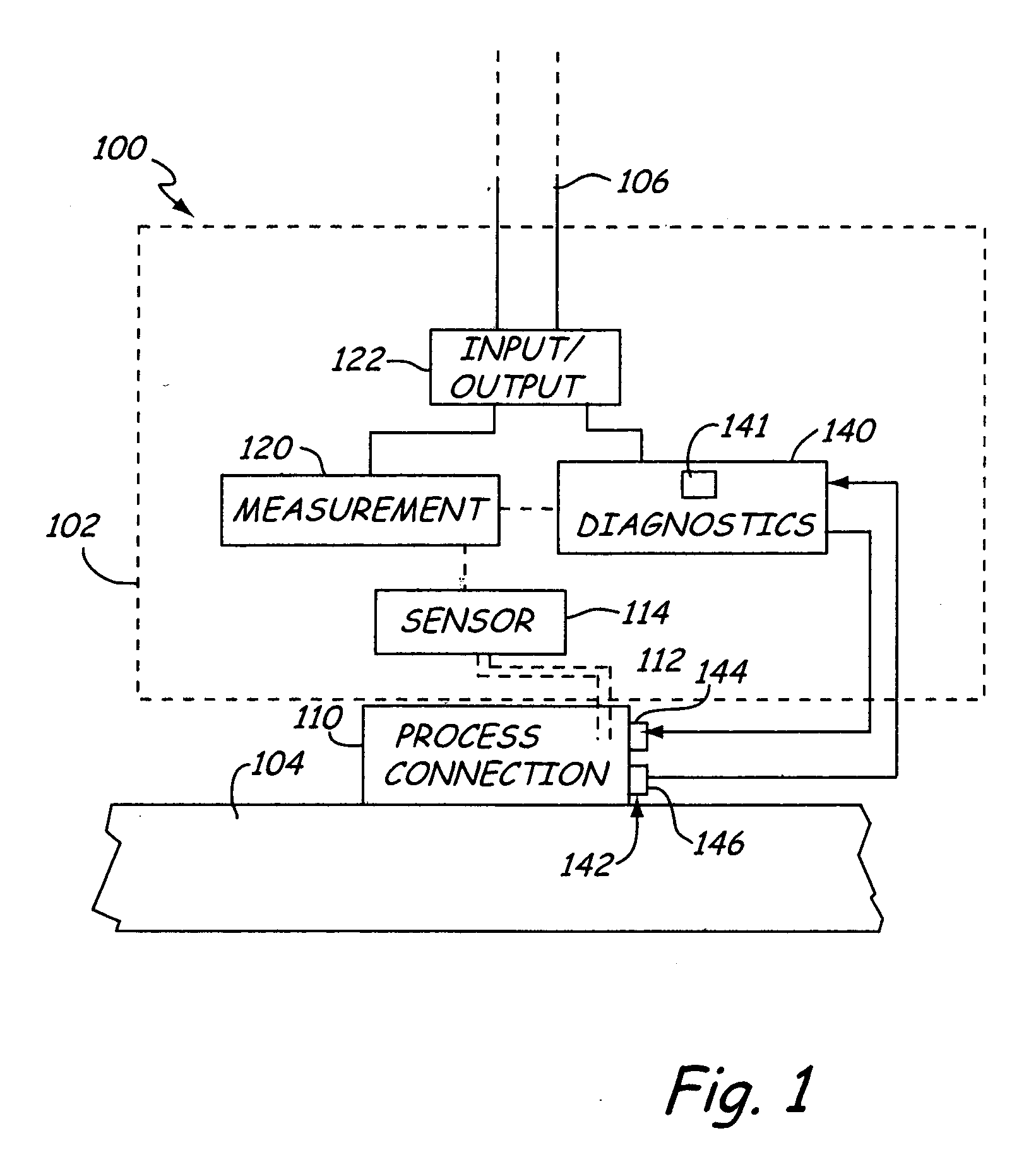
[0009]FIG. 1 is a partial view of a process control or monitoring system 100 which includes a process transmitter 102 coupled to process pipe 104. Process pipe 104 can be any type of vessel which carries process fluid including, for example, a storage container. Process pipe 104 carries a process fluid and transmitter 102 is configured to measure a process variable of the process fluid, such as pressure, and provide an output. One example output is a two-wire process control loop 106 which operates in accordance with standardized communication protocols such as the HART® Protocol, Fieldbus, Profibus, or others.

[0010] Transmitter 102 couples to the process fluid through a process connection 110. The process connection provides impulse piping 112 which extends between the process fluid and a sensor, for example a pressure sensor 114. The impulse piping 112 can be a direct fluid connection which carries process fluid and, in some embodiments, can include an isolation diaphragm if desi...


PUM


Abstract

Diagnosing operation of an impulse piping line in an industrial process is provided. A vibration source transmits a vibration signal through the piping and a vibration signal receiver receives the vibration signal. The operation of the impulse piping line is diagnosed, such as failure or impending failures, based upon the received vibration signal.

Description

BACKGROUND OF THE INVENTION [0001] The present invention relates to process devices. More particularly, the present invention relates to process devices which coupled to process fluid through process piping. [0002] Various types of process devices are used to measure process variables and couple to process fluid through process piping. For example, fluid flow meters are used in industrial process control environments to measure fluid flow and provide outputs related to flow indicators and process controllers. Inferential flow meters measure fluid flow in a pipe by measuring a pressure drop near a discontinuity within the pipe. The discontinuity (primary element) can be an orifice, a nozzle, a venturi, a pitot tube, a vortex shedding bar, a target or even a simple bend in the pipe. Flow around the discontinuity causes both a pressure drop and increased turbulence. The pressure drop is sensed by a pressure transmitter (secondary element) placed outside the pipe and connected by impuls...

Claims


Application Information

Patent Timeline
IPC IPC(8): G01F1/36G01F25/00G01L19/00G01L27/00G01N29/12G01N29/22
CPCG01F25/0007G01N2291/2634G01N29/12G01L19/0015G01F25/10
Inventor BROWN, GREGORY C.SCHUMACHER, MARK S.
Owner ROSEMOUNT INC
Why Eureka
Try Eureka