Ball machine mobility mount and a method of using it

a technology of ball machine and mount, which is applied in the field of ball machine mobility mount, can solve the problems of machine not being able to react to the movement or position of a practicing player, the feed of the ball machine is regular, predictable and expected, and the effect of reducing the predictability of the direction of the ball feed

Inactive Publication Date: 2005-06-23
WINTER THOMAS +1
View PDF13 Cites 0 Cited by
  • Summary
  • Abstract
  • Description
  • Claims
  • Application Information

AI Technical Summary

Benefits of technology

[0007] The present invention allows a ball machine to be transported and reduces the predictability of ball feed direction by allowing a ball machine to be aimed or directed manually by an operator, to do this a ball machine is temporarily mounted securely on a ball machine mobility mount.

Problems solved by technology

Practicing players suffer from the disadvantage that ball machine feeds are regular, predictable and expected.
The machines cannot react to a practicing player's movements or positions, and as a consequence cannot make decisions regarding ball placement or apply tactics according to a given situation / scenario.

Method used


Image

  • Ball machine mobility mount and a method of using it
  • Ball machine mobility mount and a method of using it
  • Ball machine mobility mount and a method of using it

Examples


Embodiment Construction

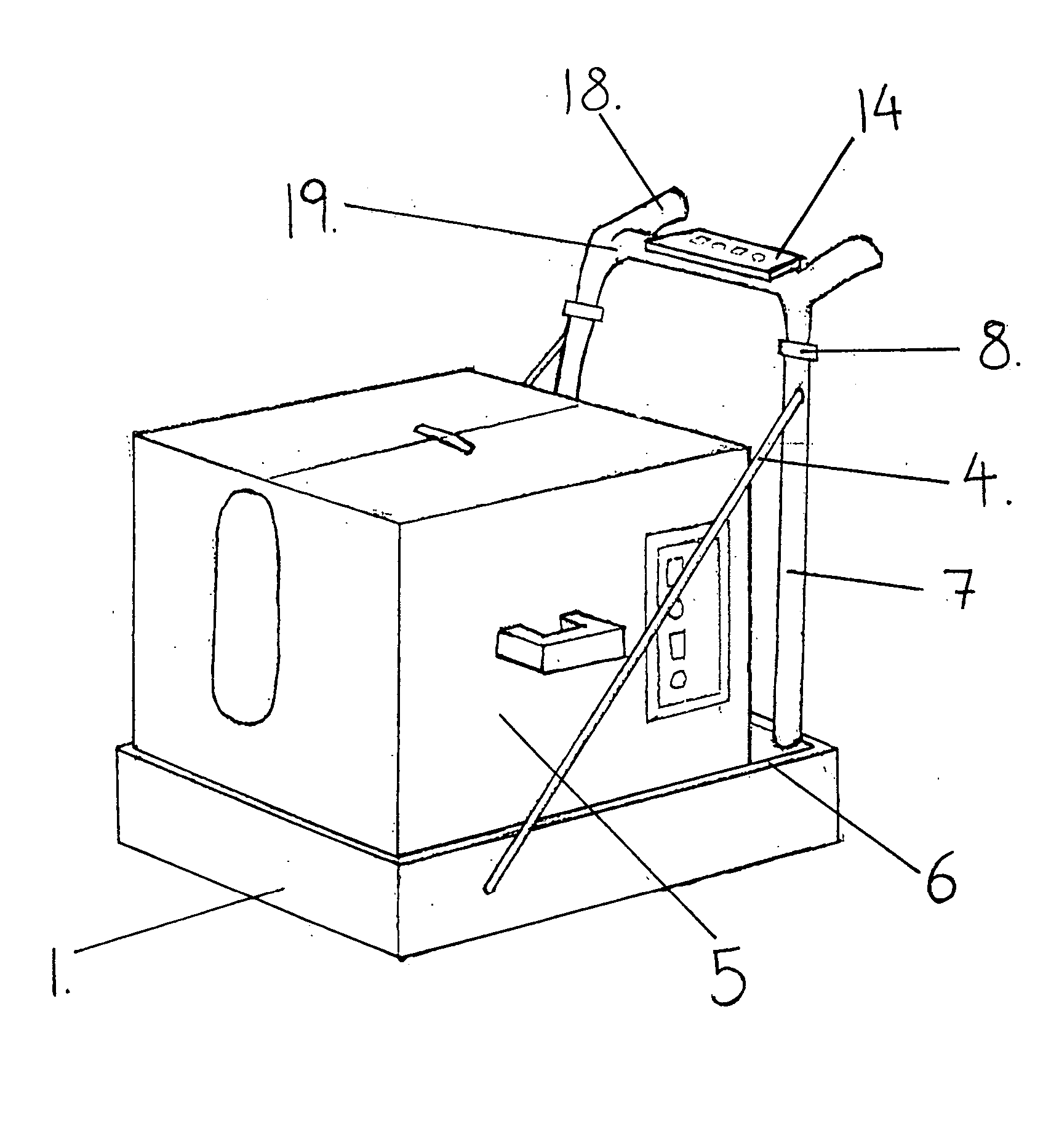
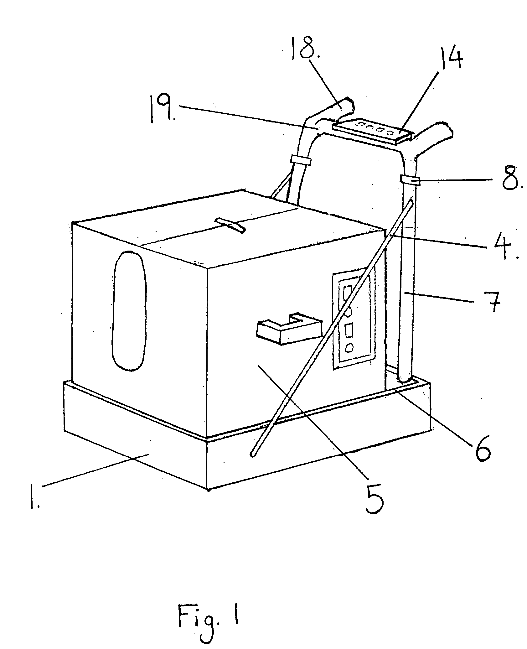
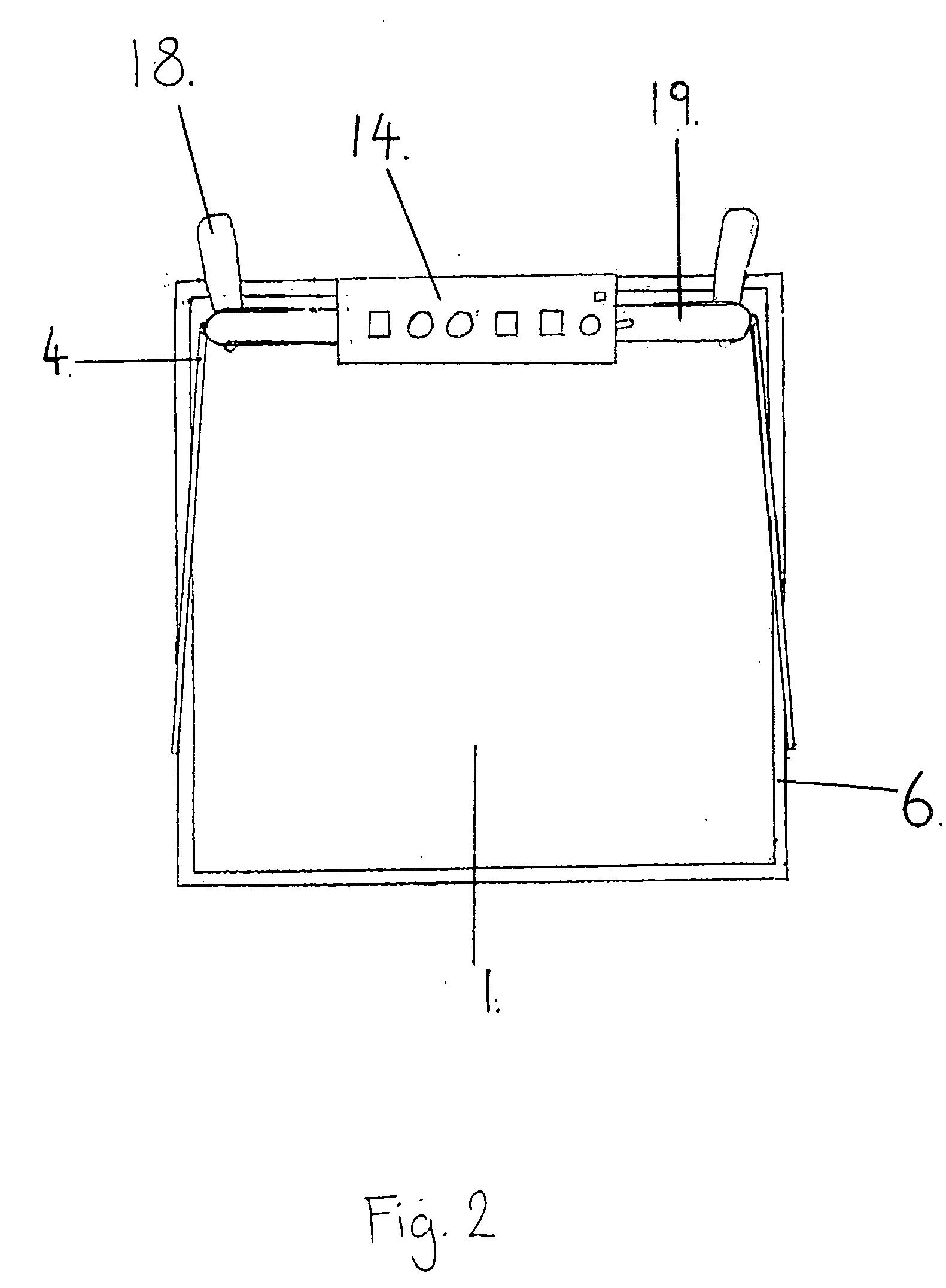
[0016] Referring to the drawings the ball machine mobility mount comprises a platform 1, to which a ball machine 5 can be temporarily mounted securely using securing devices such as a raised lip or edge 6 that runs around the perimeter of the platform which secures the ball machine 5 by wedging it in place preventing it from sliding or tipping off the platform 1, as shown in FIG. 1. The handles give an operator means to manage and control the elevation of the apparatus as well as the forward backward and rotational movement of the platform 1 and thus the ball machine 5. The handles are comprising: gripping members 18, their interconnection member 19 and sleeve members 7. The interconnection member 19 slide into sleeve members 7, to form an adjustable telescopic device, and are then locked into place via clamping devices 8, this allows the height of the handles to be adjusted to the preference of an operator. The sleeves 7 are erected and secured to the platform by snugly slotting in...


PUM


Abstract

The present invention comprises a platform on which a ball machine is temporarily mounted and can be secured. Beneath the platform a type of pivot or other variety of mobility providing device(s) is/are attached, to allow the platform to move about in multiple directions and/or rotate. The support platform can be allowed to roll, rotate, tilt and turn while a ball machine is attached to it. Handle(s) can be attached to the platform to allow someone to manually manage/dictate the aim or position of the apparatus, thus control or change the direction of each ball fed when a ball machine is in operation and attached to the structure.

Description

[0001] This application claims priority from pending United Kingdom Patent Application No.0329742.1, filed Dec. 22, 2003.BACKGROUND OF THE INVENTION [0002] 1. Field of Invention [0003] This invention relates to a ball machine mobility mount. [0004] 2. Description of Prior Art [0005] Ball machines are used in various sports as practice aids. They feed balls repeatedly to random, coincidental or pre-programmed places / positions. Some ball machines feed balls while oscillating, affecting the direction and placement of each fed ball. [0006] Practicing players suffer from the disadvantage that ball machine feeds are regular, predictable and expected. The machines cannot react to a practicing player's movements or positions, and as a consequence cannot make decisions regarding ball placement or apply tactics according to a given situation / scenario. BRIEF SUMMARY OF THE INVENTION [0007] The present invention allows a ball machine to be transported and reduces the predictability of ball feed...

Claims


Application Information

Patent Timeline
Patent Type & Authority Applications(United States)
IPC IPC(8): A63B69/40B62B1/00B62B1/10B62B5/00B62B5/06
CPCA63B69/40B62B1/00B62B1/10B62B2301/252B62B5/062B62B5/067B62B5/0026
Inventor WINTER, THOMASWINTER, GREGORY A.
Owner WINTER THOMAS
Why Eureka
Try Eureka