
Method and Systems for Laser Treatment of Presbyopia Using Offset Imaging

a laser treatment and presbyopia technology, applied in laser surgery, medical science, diagnostics, etc., can solve the problems of reducing predictability, lack of precision for a given surgical procedure, and the nature of the boundary between the optical zone and the untreated, so as to inhibit presbyopia and minimize vision degradation.

Inactive Publication Date: 2014-04-10
AMO MFG USA INC
View PDF2 Cites 2 Cited by
  • Summary
  • Abstract
  • Description
  • Claims
  • Application Information

AI Technical Summary

Benefits of technology

This approach provides precise and predictable refractive corrections by accounting for corneal healing, maintaining optimal vision by balancing near and far-vision corrections and minimizing glare, while ensuring the cornea heals to an aspheric shape that corrects presbyopia effectively.

Problems solved by technology

One of the major difficulties encountered in the application of laser surgery techniques to effect hyperopic and presbyopic refractive error corrections lies in the nature of the boundary between the optical zone and the untreated area.
This natural phenomenon, sometimes termed the “hyperopic shift” in phototherapeutic keratectomy, causes a lack of precision for a given surgical procedure and diminished predictability, counteracting the beneficial effects of the refractive correction procedure and thereby reducing the desirability of the procedure to the prospective patient.

Method used


Image

  • Method and Systems for Laser Treatment of Presbyopia Using Offset Imaging
  • Method and Systems for Laser Treatment of Presbyopia Using Offset Imaging
  • Method and Systems for Laser Treatment of Presbyopia Using Offset Imaging

Examples


Embodiment Construction

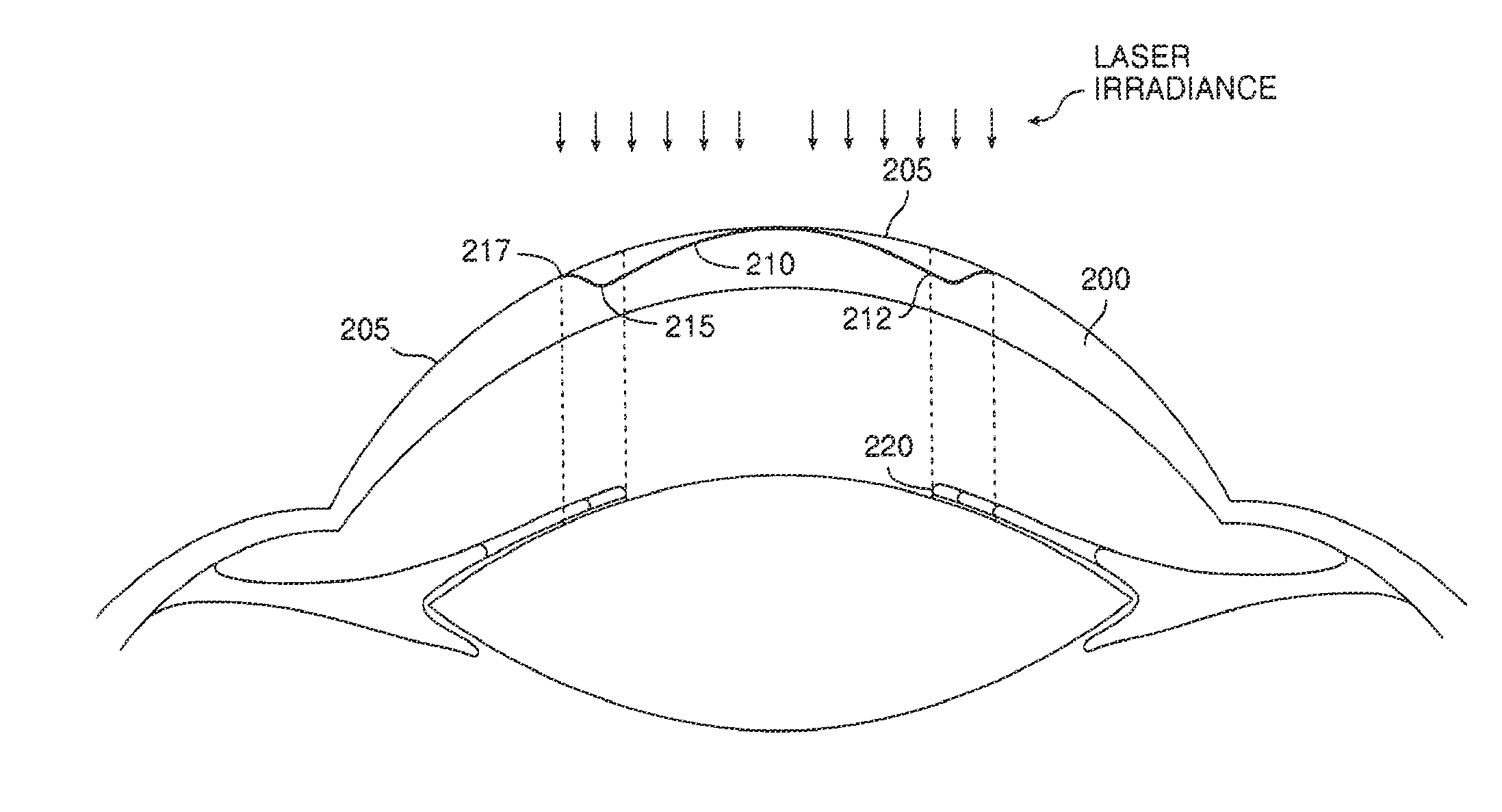
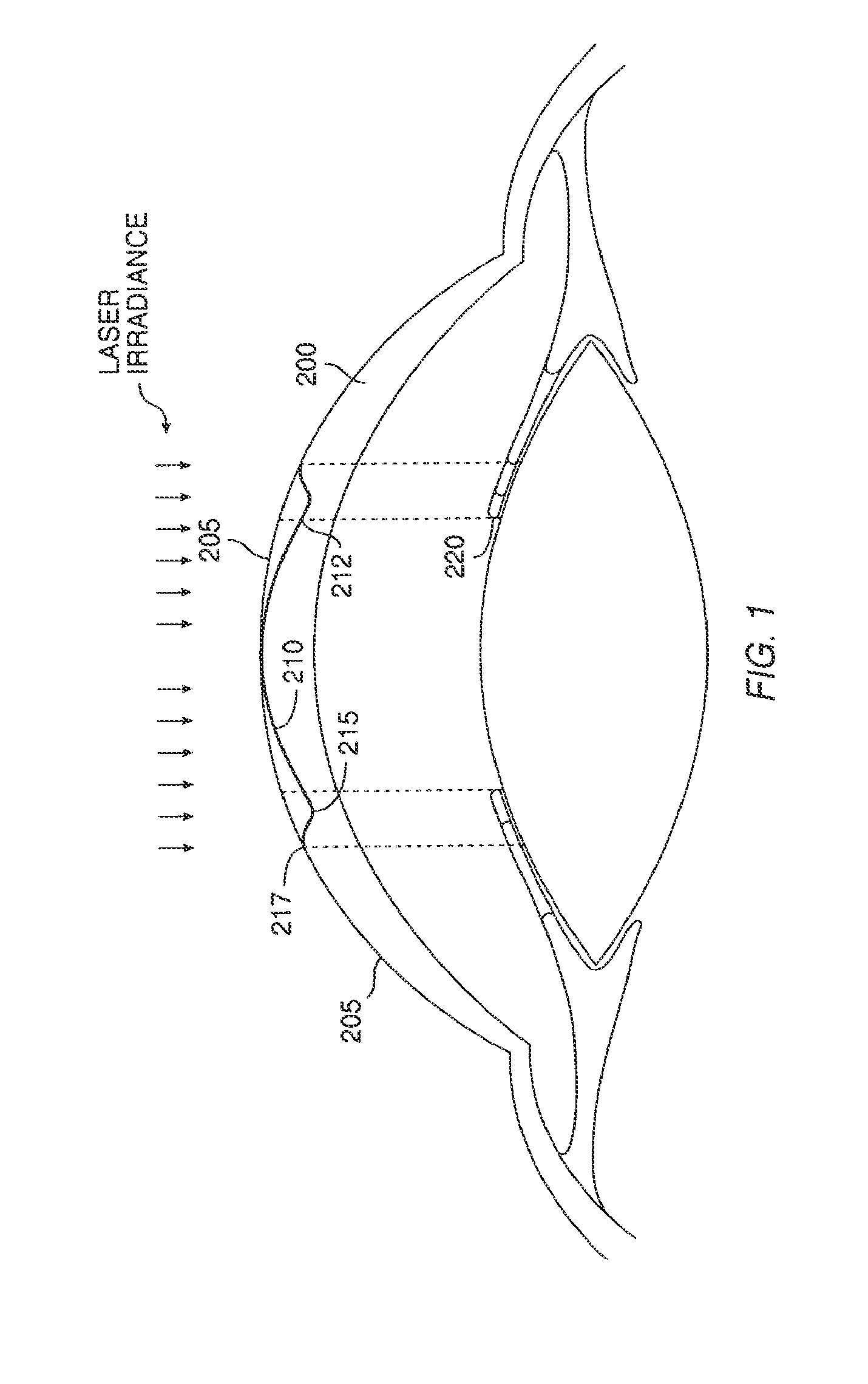
[0049]Turning now to the drawings, FIG. 1 illustrates a schematic side view of a cornea 200 treated with the invention. The cornea 200 has an anterior surface that provides most of the refractive power of the eye. The initial anterior surface 205 of the cornea 200 has been reshaped to a desired healed profile. The desired healed profile includes anterior optical surface 210 and anterior transition surface 215. The anterior optical surface 210 has a multifocal aspheric shape that corrects for near-vision centrally and far-vision peripherally.

[0050]While the present invention will often be described with reference to the mitigation of presbyopia in combination with refractive hyperopia treatment, it should be understood that the benefits of the present invention are not limited to these specific procedures. These presbyopia treatment techniques may be used when no other refractive correction (other than the correction, mitigation, and / or inhibition of presbyopia) is desired, or the pr...


PUM


Abstract

An ophthalmic surgery system and method for treating presbyopia by performing ablative photodecomposition of the corneal surface. The offset image of a variable aperture, such as a variable width slit and variable diameter iris diaphragm, is scanned in a preselected pattern to perform ablative sculpting of predetermined portions of a corneal surface. The scanning is performed to ablate an optical zone sized to match the patient pupil with a peripheral transition zone outside the pupil. The shape of the ablated optical zone is different from the shape of the final optical correction on the anterior surface of the cornea. The optical zone corrects for near-vision centrally and far-vision peripherally. A movable image displacement mechanism enables radial displacement and angular rotation of the profiled beam exiting from the variable aperture. The invention enables wide area treatment with a laser having a narrower beam than the treatment area, and can be used in the treatment of many conditions in conjunction with presbyopia such as hyperopia, hyperopic astigmatism and irregular refractive aberrations.

Description

CROSS-REFERENCES TO RELATED APPLICATIONS[0001]The present application is a continuation of U.S. Ser. No. 12 / 436,736 filed May 6, 2009, which is a continuation of U.S. Ser. No. 10 / 600,027 filed Jun. 19, 2003 (Abandoned), which is a continuation of U.S. Ser. No. 09 / 901,964 filed Jul. 9, 2001 (now U.S. Pat. No. 6,663,619), which is a division of U.S. Ser. No. 09 / 261,768 filed Mar. 3, 1999 (now U.S. Pat. No. 6,280,435), which claims the benefit of U.S. 60 / 076,786 filed Mar. 4, 1998. The full disclosures, each of which are incorporated herein by reference in their entirety for all purposes.BACKGROUND OF THE INVENTION[0002]1. Field of the Invention[0003]This invention relates to surgical modifications to the eye. In a specific embodiment, the invention provides ophthalmic surgery techniques which employ a laser to effect ablative photodecomposition of corneal tissue to correct presbyopia and / or other vision defects.[0004]With aging, a condition of the eye known as presbyopia develops. Wit...

Claims


Application Information

Patent Timeline
Patent Type & Authority Applications(United States)
IPC IPC(8): A61F9/008A61F9/007A61B3/10A61F9/01A61N5/06
CPCA61F9/00802A61F9/008A61F9/00806A61F9/00808A61F9/00817A61F2009/00844A61F2009/00872A61F2009/0088A61F2009/00882A61F2009/00895
Inventor ODRICH, MARCGREENBERG, KENNETHLEGERTON, JEROME A.MUNNERLYN, CHARLES R.SHIMMICK, JOHN K.
Owner AMO MFG USA INC
Learn More