Amusement apparatus

a technology for amusement equipment and games, applied in the field of amusement equipment, can solve the problems of increasing audience participation, unable to fully engage or induce audience participation or anticipation, and known to tempt those of less than sterling character to cheat, so as to avoid cheating by players, increase audience participation, and be genuinely entertaining and enjoyable

Inactive Publication Date: 2008-05-15
JOHNSTON ROY
View PDF9 Cites 0 Cited by
  • Summary
  • Abstract
  • Description
  • Claims
  • Application Information

AI Technical Summary

Benefits of technology

[0019]The embodiment of the amusement apparatus and method of using same illustrated herein and as exemplified in FIGS. 1-8 solves multiple problems that are inherent in the prior art. One problem solved is that of player control and the avoidance of player cheating. Another problem solved is increasing audience participation. “Money machines” as found in the present art are genuinely entertaining and enjoyable for the player 6 and non-player(s) or audience that may be watching. The prize 20 won by “money machine” player 6 is based in part on chance and in part on skill. For example, a player 6 having long arms 7 and excellent hand eye coordination (not shown) can gather more prizes 20 (i.e. money) during the time allowed than a player 6 having short arms and poor hand eye coordination (not shown). This is an acceptable part of amusement apparatus operation. The opportunity for a player 6 to get “lucky” based on that particular individual player's skill adds to the drama and entertainment of the game for the player 6 and the non-player(s) 22 watching. The lure of getting “lucky” in the prior art amusement apparatus, however, has been known to tempt those of less than sterling character to “cheat.”
[0020]A common way that player's may cheat money machines of the prior art is to begin grabbing at the circulating prizes 20 before the air blower has fully delivered the amount of air necessary to fully and uniformly distribute and circulate the prizes within the money machines of the prior art. The opportunity for a player 6 to cheat decreases the predictability of player outcomes and thus a prospective money machine owner's enthusiasm for investing in a money machine or increasing the potential to win large sums by legitimate play of the game. The money machine game of the prior art is also entertaining to those watching but at present does not fully engage or induce audience participation or anticipation.
[0021]Upon activation of the game start sequence, the air blower starts and air flow into the transparent cube begins. After the air blower starts, there is a period of time where the bills are not circulating properly and a player may simply grab them off the floor. The density of the circulating bills is high at this time so every grab by the player produces an increased number of bills in comparison to when the air is properly circulating. In the prior art, a player would take advantage this lower flow rate for increased gains. Or after playing once, the player may realize that at the start of the game the bills will clump in a dense “ball” thereby increasing the potential for excess recovery by grabbing at the floor. No skill or luck is involved at this point.
[0022]In the present art having FunStart™ technology, the player must continue to contact or engage the engagement system 10 incorporating FunStart™ technology located within the interior space 4 (as illustrated by the player console 13 as shown in FIG. 5) until allowed to disengage the engagement system 10 at which time prize 20 circulation is uniform. If the player 6 does not follow the preceding protocol, the air circulation system 9 will stop and the game will be over before it begins. An advantage of the present art then is to increase in consistency of the results. This allows an opportunity to create other hybrid uses for the amusement apparatus 1.
[0023]The amusement apparatus 1 disclosed herein is designed to generate excitement on both the part of the users and audience the surrounding the money machine. This concept is well known in the prior art, thus the use of transparent glass or Lexan® plastic for walls of the money machine. The present art takes audience participation one step further by increasing communication with the audience regarding the game to be played.
[0024]As embodied by FIGS. 1-8, the amusement apparatus of the present art may be configured with a “Christmas Tree” type lighting concept for enhanced audience participation. Similar to the lighting system used at a drag strip to coordinate and initiate the start of a drag race to a driver, the Christmas tree lighting system of the present art works with the hand based FunStart™ player control system to communicate to the audience that play is about to begin through an illuminated countdown system. Applicant has branded this feature as FunVision™ and is one embodiment of a signaling system 11 as found in the present art. This system may be integrated with a countdown timer on the player controls. This can be accomplished through a combination of a countdown timer and lights of changing color. Although not shown, but understood by those of ordinary skill in the art, FunVision™ may be further enhanced through the addition of an audio system. It is also possible with FunVision™ as disclosed in the present art to include additional game features such as the amount played for, the amount won or increase audience enjoyment by including novelty theme based sounds. This technology of the amusement apparatus builds both audience and player anticipation and excitement.

Problems solved by technology

One problem solved is that of player control and the avoidance of player cheating.
Another problem solved is increasing audience participation.
The lure of getting “lucky” in the prior art amusement apparatus, however, has been known to tempt those of less than sterling character to “cheat.”
The money machine game of the prior art is also entertaining to those watching but at present does not fully engage or induce audience participation or anticipation.
After the air blower starts, there is a period of time where the bills are not circulating properly and a player may simply grab them off the floor.

Method used


Image

  • Amusement apparatus
  • Amusement apparatus
  • Amusement apparatus

Examples


Embodiment Construction

—BRIEF DESCRIPTION OF THE FIGURES

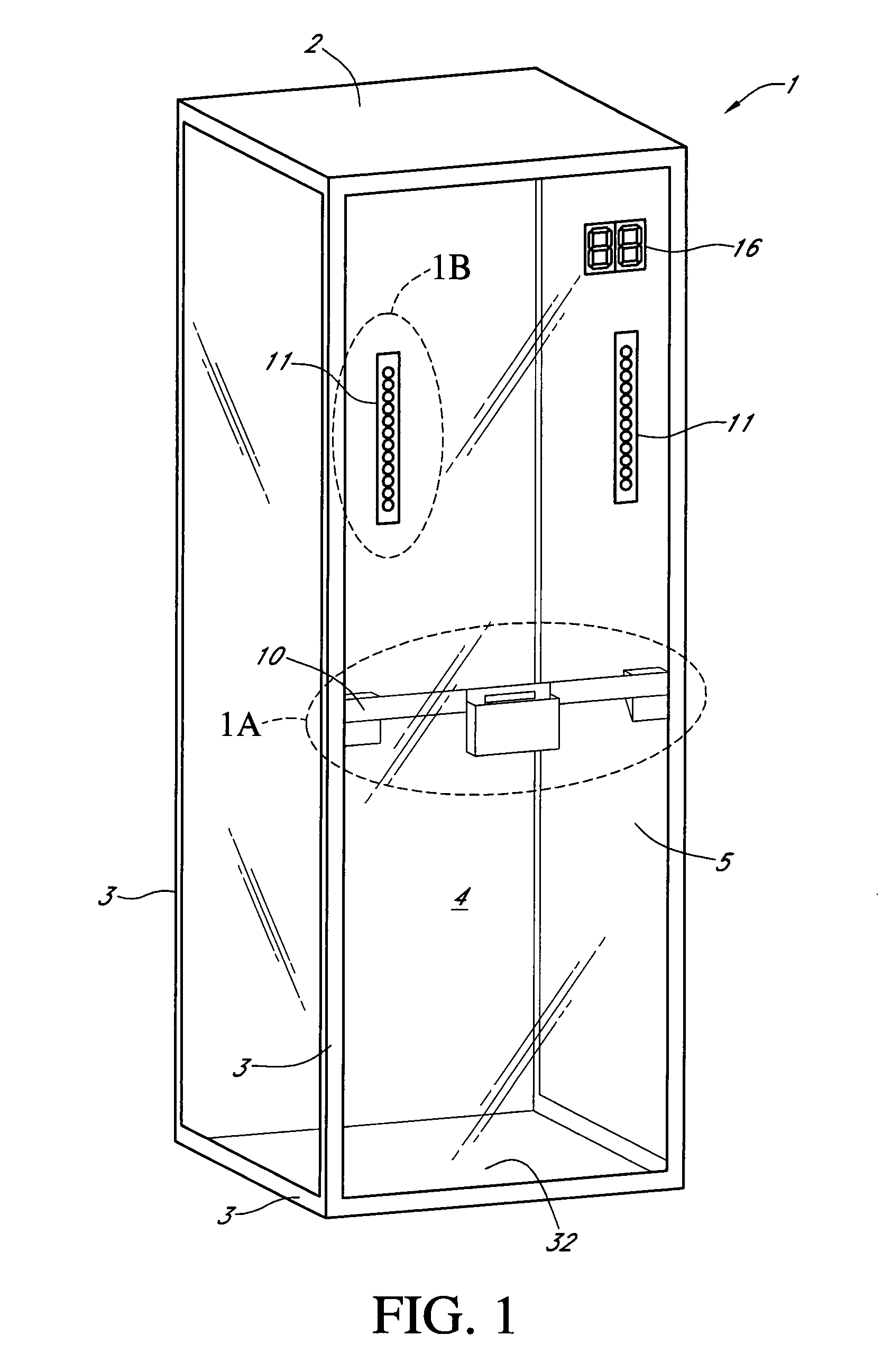
[0006]FIG. 1 is an isometric view of one embodiment of an amusement apparatus.

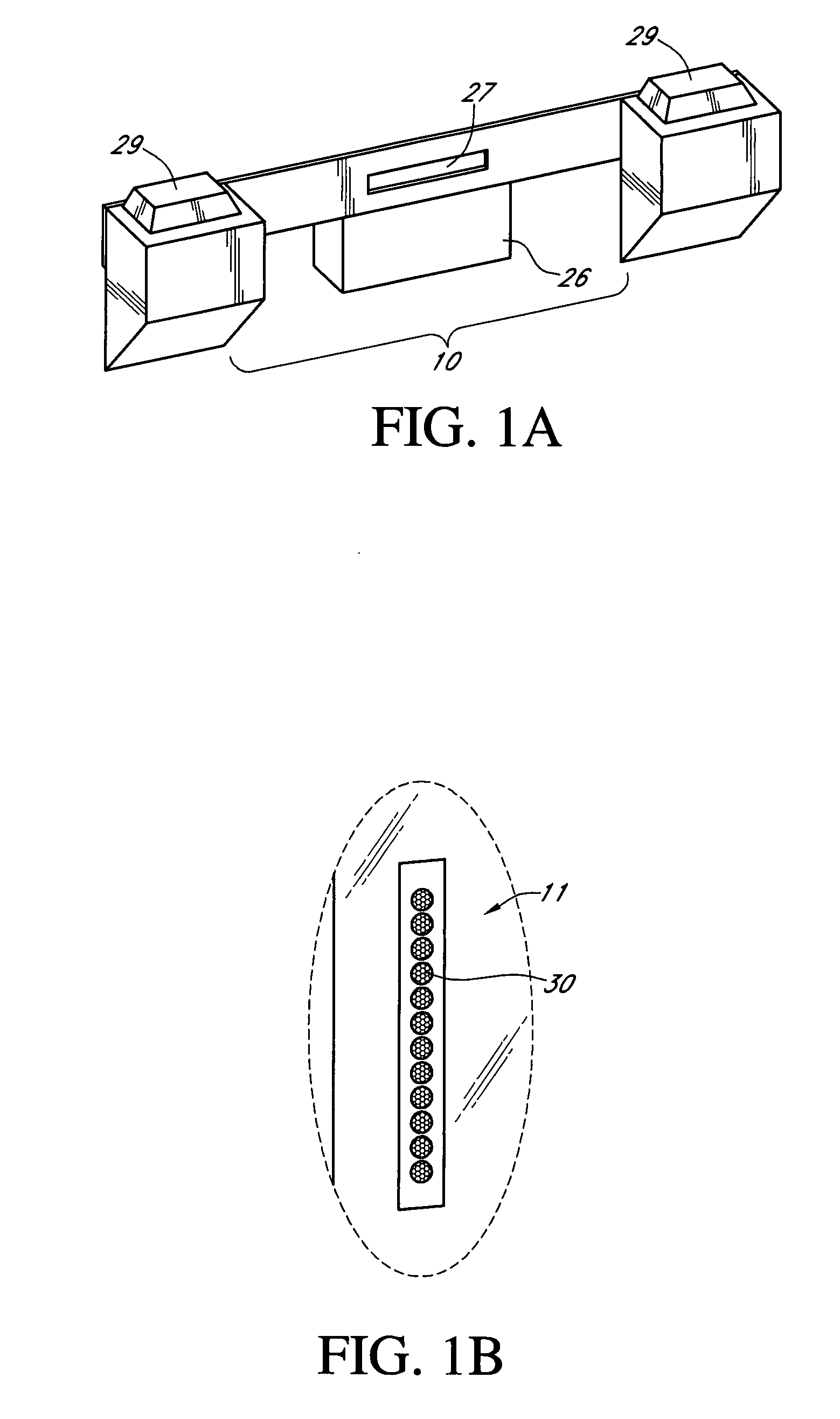
[0007]FIG. 1A is a detailed view of one embodiment of an engagement system for the amusement apparatus of FIG. 1.

[0008]FIG. 1B is a detailed view of one embodiment of a signaling system for the amusement apparatus of FIG. 1.

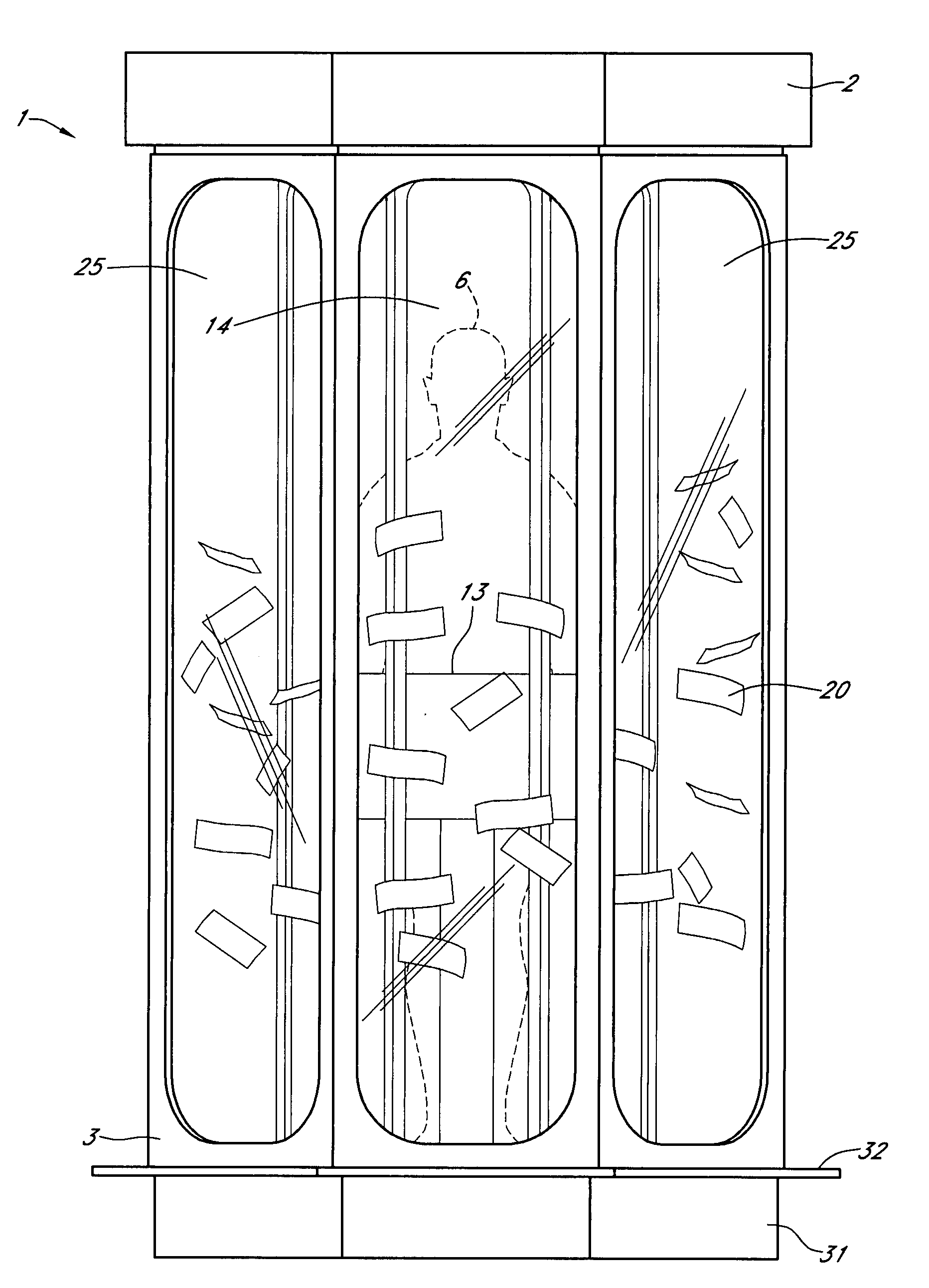
[0009]FIG. 2 is an isometric view of one embodiment of an amusement apparatus with a player positioned therein.

[0010]FIG. 2A is a detailed view of one embodiment of an engagement system for the amusement apparatus of FIG. 2.

[0011]FIG. 2B is a detailed view of one embodiment of a signaling system for the amusement apparatus of FIG. 2.

[0012]FIG. 3 is a front view of another embodiment of an amusement apparatus.

[0013]FIG. 4 is an isometric view of another embodiment of an amusement apparatus.

[0014]FIG. 5 is a detailed view of another embodiment of an engagement system for an amusement apparatus from the perspective of a player.

[0015]FIG. 6 is a left-side re...


PUM


Abstract

The amusement apparatus comprising a housing, a frame and an interior space, and a door allowing entry of a player having arms into interior space. An air circulation system fluidly connected to interior space of housing. An engagement system located within interior space. Engagement system, control system, signaling system and an air circulation system are cooperatively interconnected. A player area is located within the interior space and positioned proximate the engagement system wherein contact by player with engagement system initiates a sequence of instructions from the control system to initiate the delivery of air into interior space by air circulation system for circulation of prizes within interior space. A signal to player is sent via signaling system to discontinue player contact with engagement system so player may interact with the prizes circulating in the interior space for the purpose of removing the prizes from the housing via the interior space.

Description

CROSS REFERENCE TO RELATED APPLICATIONS[0001]Applicant claim priority under 35 U.S.C. § 119(e) of provisional U.S. Patent Application Ser. No. 60,857,947 filed on Nov. 10, 2006 entitled “Improved Money Machine” which is incorporated by reference herein.FIELD OF THE INVENTION[0002]The present invention relates to a method and apparatus to improve fan driven money (prize) circulation machines. The present device is envisioned to be used in and for gambling, participant enjoyment, entertainment and or charitable or fundraising projects.STATEMENT REGARDING FEDERALLY SPONSORED RESEARCH OR DEVELOPMENT[0003]No federal funds were used to develop or create the invention disclosed and described in the patent application.REFERENCE TO SEQUENCE LISTING, A TABLE, OR A COMPUTER PROGRAM LISTING COMPACT DISK APPENDIX[0004]Not ApplicableAUTHORIZATION PURSUANT TO 37 C.F.R. §1.171 (d)(c)[0005]A portion of the disclosure of this patent document contains material which is subject to copyright and tradema...

Claims


Application Information

Patent Timeline
Patent Type & Authority Applications(United States)
IPC IPC(8): A63G31/00
CPCA63J99/00A63G31/00
Inventor JOHNSTON, ROY
Owner JOHNSTON ROY
Why Eureka
Try Eureka