Apparatus and method for producing variable intensity of light

Inactive Publication Date: 2005-06-23
NOKIA TECHNOLOGLES OY
View PDF9 Cites 38 Cited by
  • Summary
  • Abstract
  • Description
  • Claims
  • Application Information

AI Technical Summary

Benefits of technology

[0007] It is an objective of the present invention to provide an apparatus and a method for producing a variable intensity of light emitted at the user interface of a portable electronic device. A specific objective of the present inven

Problems solved by technology

The drawbacks of the prior art arrangements become apparent when a question is raised about the number of different intensity levels that can be obtained.
These may well be enough for providing

Method used


Image

  • Apparatus and method for producing variable intensity of light
  • Apparatus and method for producing variable intensity of light
  • Apparatus and method for producing variable intensity of light

Examples


Embodiment Construction

[0046] The exemplary embodiments of the invention presented in this patent application are not to be interpreted to pose limitations to the applicability of the appended claims. The verb “to comprise” is used in this patent application as an open limitation that does not exclude the existence of also unrecited features. The features recited in depending claims are mutually freely combinable unless otherwise explicitly stated.

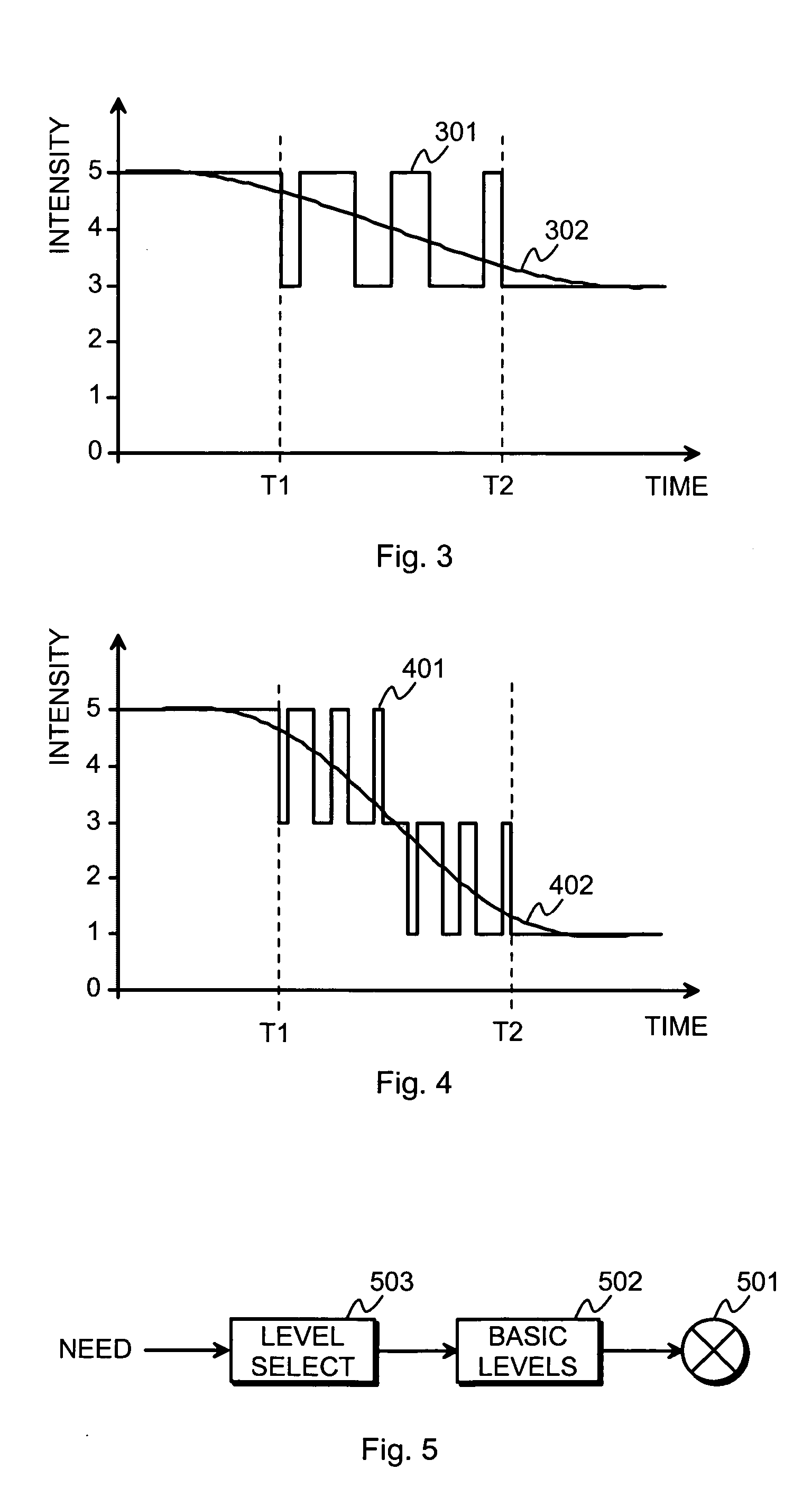
[0047]FIG. 3 illustrates a principle of using variable temporal multiplexing and integration to obtain a smooth change between two intensity levels. The horizontal axis represents time, and the vertical axis represents lighting intensity in some arbitrary units. We may assume that a combination of a basic lighting controller and a light source connected thereto is able to produce an intensity of 5 units or an intensity of 3 units. At the beginning of the process the output intensity is constant at 5 units. At time T1 there is started a switching sequence during...


PUM


Abstract

A lighting control arrangement controls the user interface lighting in a portable electronic device. An output of the lighting control arrangement selectively provides lighting intensity commands to a lighting controller. Each of the lighting intensity commands indicates one of certain basic lighting intensity levels. A level selector repeatedly changes, at a frequency that is higher than an integration frequency of a human visual system, the lighting intensity command to be provided at said output.

Description

TECHNICAL FIELD [0001] The invention concerns generally the technical field of varying the intensity of light emitted by a light source. Especially the invention concerns the problem of obtaining a large selection of different light intensities from a light source with a simple controlling arrangement. BACKGROUND OF THE INVENTION [0002] In a large variety of applications it is desirable to be able to control the intensity of light emitted by an electrically driven light source. The present invention concerns especially the user interfaces of portable electronic apparatuses, where artificial illumination is used to enhance the usability of the user interface when ambient light is not enough, and to increase visual attractiveness. Typical illuminated user interface components include but are not limited to displays and keypads. Light sources are typically either discharge tubes or LEDs (Light Emitting Diodes). [0003]FIG. 1 illustrates a known principle of providing controllable illumi...

Claims


Application Information

Patent Timeline
IPC IPC(8): H05B44/00H05B41/392
CPCH05B41/3925H05B41/3921H05B41/38H05B41/36H05B41/39H05B41/392
Inventor LINDQVIST, TIMO T.
Owner NOKIA TECHNOLOGLES OY
Why Eureka
Try Eureka