Sensor for coordinate input device

a technology of input device and sensor, which is applied in the direction of static indicating device, using reradiation, instruments, etc., can solve the problems reducing the invalid area, increasing the detectable area, etc., and reducing the overall size of the sensor. , the effect of reducing the overall size of the sensor

Active Publication Date: 2005-06-23
WACOM CO LTD
View PDF4 Cites 1 Cited by
  • Summary
  • Abstract
  • Description
  • Claims
  • Application Information

AI Technical Summary

Benefits of technology

[0020] According to the present invention, a terminal connected to signal detection lines as well as the lines that provide connections between the terminal and the signal detection lines can both be provided within a region where the signal detection lines are arranged. Thus, a region that the signal detection lines cannot use in the sensor to detect signals can be substantially eliminated, and substantially the entire surface of the sensor can be used as a region for detecting signals. This arrangement allows very efficient use of a space of the sensor and also can ensure a large detectable area while reducing the overall size of the sensor.
[0021] According to the present invention, a terminal connected to loop coils as well as lines that provide connections between the terminal and the loop coils can both be provided within a region where the loop coils are arranged. Thus, a region that the loop coils cannot use in the sensor to detect signals can be substantially eliminated, and substantially the entire surface of the sensor can be used as a region for detecting signals. This arrangement allows very efficient use of a space of the sensor and also can ensure a large detectable area while reducing the overall size of the sensor.
[0022] According to the sensor of the present invention, the terminal portion is disposed between the linear sections of two adjacent loop coils of the x-direction loop coil group at an edge portion of the x-direction loop coil group or in the vicinity of the edge portion. The terminal portion may also be disposed between the linear sections of two adjacent loop coils of the y-direction loop coil group at an edge portion of the y-direction loop coil group or in the vicinity of the edge portion. That is, the terminal portion is provided at a portion where adjacent linear sections are arranged at a large interval. As a result, it is possible to easily provide a terminal portion having a large number of terminals. Also, since the spacing between the adjacent liner sections at the portion where the terminal portion is disposed is large, it is possible to easily and freely arrange the lines that provide connections between the terminals of the terminal portion and the corresponding loop coils.
[0023] According to the sensor of the present invention, the terminal portion includes a plurality of terminals exposed at a surface of the sensor. A shield plate is disposed at a reverse side of the surface at which the plurality of terminals are exposed. Consequently, other wires can be easily connected to the terminals of the terminal portion. A control circuit substrate connected via those wires can be laminated and fixed to a shield plate. This arrangement can provide a sensor for a coordinate input device that allows easy connection of a control circuit or the like. The sensor can be accommodated in a small space when a control circuit or the like is connected.
[0024] According to the sensor of the present invention, a flexible cable having wires for sending signals to the loop coils of the x-direction loop coil group and the y-direction loop coil group and for extracting signals from the loop coils is connected to the terminals of the terminal portion by an anisotropic conductive film (ACF) method. This arrangement significantly facilitates the connection of other wires to the terminal portion. Thus, it is possible to provide a sensor for a coordinate input device that allows easy connection of an external circuit such as a control circuit.
[0025] According to the sensor of the present invention, the terminal portion and the loop coils of the x-direction loop coil group and the y-direction loop coil group are formed as patterns on a low-cost and high-rigidity rigid substrate such as a glass epoxy substrate. Thus, the substrate can be directly secured to a housing or the like by screwing or any manner known in the art, unlike a case in which a flexible substrate or the like is used. This arrangement can simplify the configuration of an apparatus using the sensor of the present invention and thus can reduce the failure rate, reduce the cost, and increase the design freedom of the apparatus.

Problems solved by technology

For the coordinate input device, increasing the detectable area that can be used for the operation of the position indicator and reducing the overall size are major challenges.
However, an increase in the detectable area and a reduction in the invalid area, as described above, are still major challenges.

Method used


Image

  • Sensor for coordinate input device
  • Sensor for coordinate input device
  • Sensor for coordinate input device

Examples


Embodiment Construction

)

[0033] An embodiment of the present invention will be described below with reference to the accompanying drawings.

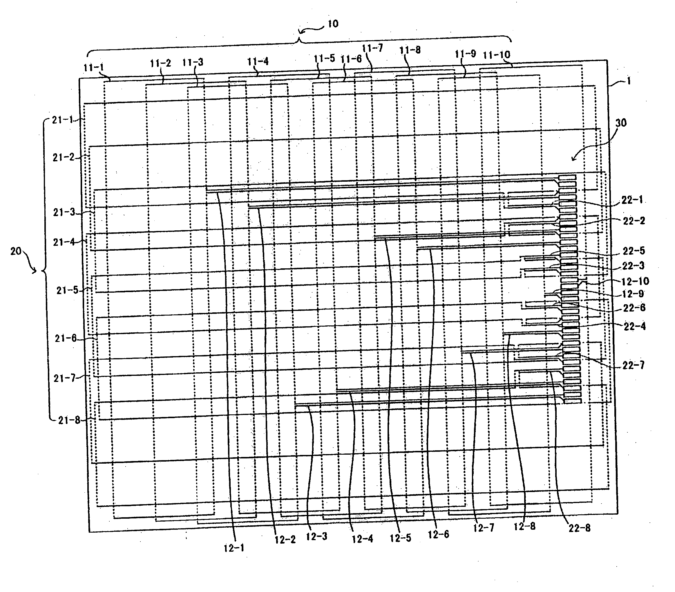
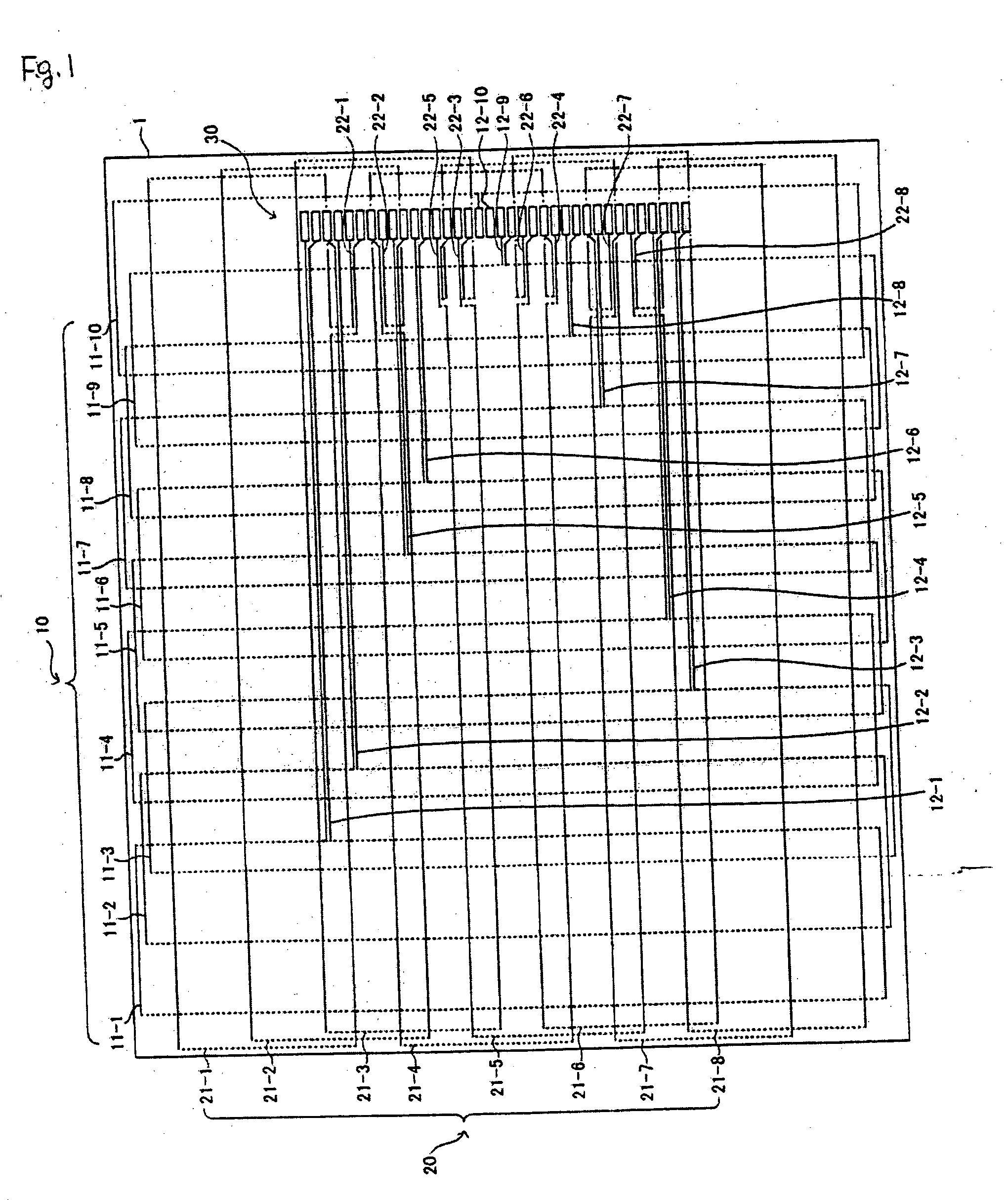
[0034]FIG. 1 is a plan view showing the configuration of a sensor 1 for a coordinate input device according to an embodiment of the present invention. In FIG. 1, reference numeral 10 indicates an x-direction loop coil group and reference numeral 20 indicates a y-direction loop coil group.

[0035] The sensor 1 includes, for example, a rigid substrate, such as a glass epoxy substrate. The solid lines and the dotted lines shown in FIG. 1 indicate wires provided on the substrate. The substrate of the sensor 1 has a plurality of layers and the wires indicated by the solid lines and dotted lines in FIG. 1 are provided by patterns in different layers. Both of the wires indicated by the solid lines and the wires indicated by the dotted lines in FIG. 1 are coated with insulating films and are not exposed at a surface of the sensor 1.

[0036] A shield plate 13 (see FIG. 4) is lami...


PUM


Abstract

A sensor for a coordinate input device includes an x-direction loop coil group including a plurality of loop coils arranged in an x direction, each loop coil having at least two linear sections perpendicular to the x direction, and a y-direction loop coil group including a plurality of loop coils arranged in a y direction, each loop coil having at least two linear sections perpendicular to the y direction. A terminal portion including a plurality of terminals is provided in the vicinity of an edge portion of the x-direction or y-direction loop coil group. Lines are disposed between the linear sections of the loop coils of the x-direction loop coil group or the y-direction loop coil group to provide connections between the terminals of the terminal portion and the corresponding loop coils of the x-direction loop coil group and the y-direction loop coil group.

Description

CROSS-REFERENCE TO RELATED APPLICATIONS AND CLAIM TO PRIORITY [0001] This application claims the benefit under 35 U.S.C. § 119 of application number 2003-400370, filed Nov. 28, 2003 in Japan, the disclosure of which is incorporated herein by reference. [0002] 1. Field of the Invention [0003] The present invention relates to a sensor for a coordinate input device using an electromagnetic effect. [0004] 2. Background of the Invention [0005] Conventional coordinate input devices are well known in the prior art. These devices use a sensor that has a large number of loop coils arranged in x and y directions and a position indicator that includes a coil. In these coordinate input devices, a sensor detects a position indicated by the position indicator using an electromagnetic effect between the sensor and the position indicator. [0006] The sensor used by the coordinate input device must have lines for supplying power to the respective loop coils and for extracting signals from the loop co...

Claims


Application Information

Patent Timeline
Patent Type & Authority Applications(United States)
IPC IPC(8): G06F3/046G06F3/033
CPCG06F3/046
Inventor KATSUHITO, OBLHORIE, TOSHIHIKOTAKESHI, KOBORL
Owner WACOM CO LTD
Why Eureka
Try Eureka