Master medium for magnetic transfer and magnetic disk and magnetic disk drive

a magnetic transfer and master medium technology, applied in the field of magnetic transfer apparatuses, can solve problems such as disturbing the servo control of the head, and achieve the effect of sufficient intensity or strength

Inactive Publication Date: 2005-06-23
TOSHIBA STORAGE DEVICE CORP
View PDF14 Cites 4 Cited by
  • Summary
  • Abstract
  • Description
  • Claims
  • Application Information

AI Technical Summary

Benefits of technology

[0007] It is accordingly an object of the present invention to provide a master medium contributing to a reliable elimination of an additional weak magnetic pole during establishment of a servo region on a magnetic recording medium. It is also an object of the present invention to provide a magnetic disk drive reliably enabling a head to follow a recording track at a higher accuracy irrespective of presence of an additional weak magnetic pole.

Problems solved by technology

This mistake will disturb the servo control of the head.

Method used


Image

  • Master medium for magnetic transfer and magnetic disk and magnetic disk drive
  • Master medium for magnetic transfer and magnetic disk and magnetic disk drive
  • Master medium for magnetic transfer and magnetic disk and magnetic disk drive

Examples


first embodiment

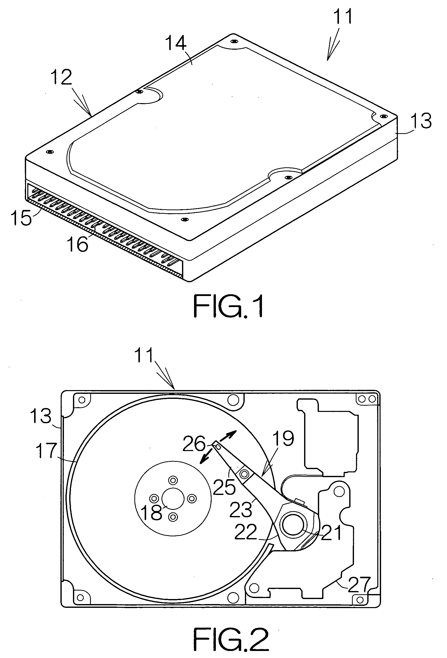
[0056]FIG. 1 schematically illustrates the outline of a hard disk drive (HDD) 11 as an example of a magnetic recording drive or storage device according to the present invention. The HDD 11 includes a box-shaped enclosure 12. The enclosure 12 includes an enclosure body 13 defining an inner space of a flat parallelepiped, for example. The enclosure body 13 may be made of a metallic material such as aluminum, for example. Molding process may be employed to form the enclosure body 13. A cover 14 is coupled to the enclosure body 13, so that the inner space of the enclosure body 13 is airtightly isolated from the exterior space. The cover 14 may be formed of a single plate material based on pressing process, for example. The plate material may be a layered material having a damping property to vibration.

[0057] The HDD 11 allows elimination of a bore, receiving an insert pin, from the cover 14 of the enclosure 12. The structure of the cover 14 is simplified. The simplified structure leads...

second embodiment

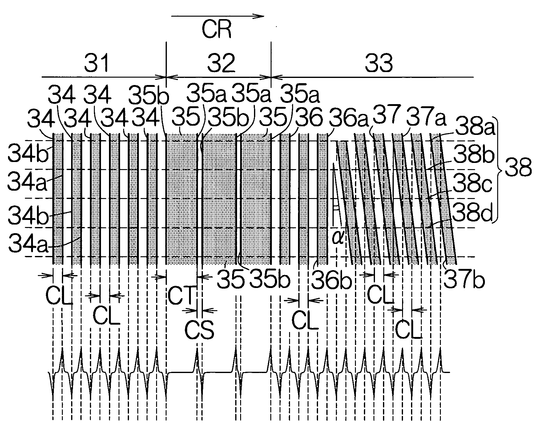
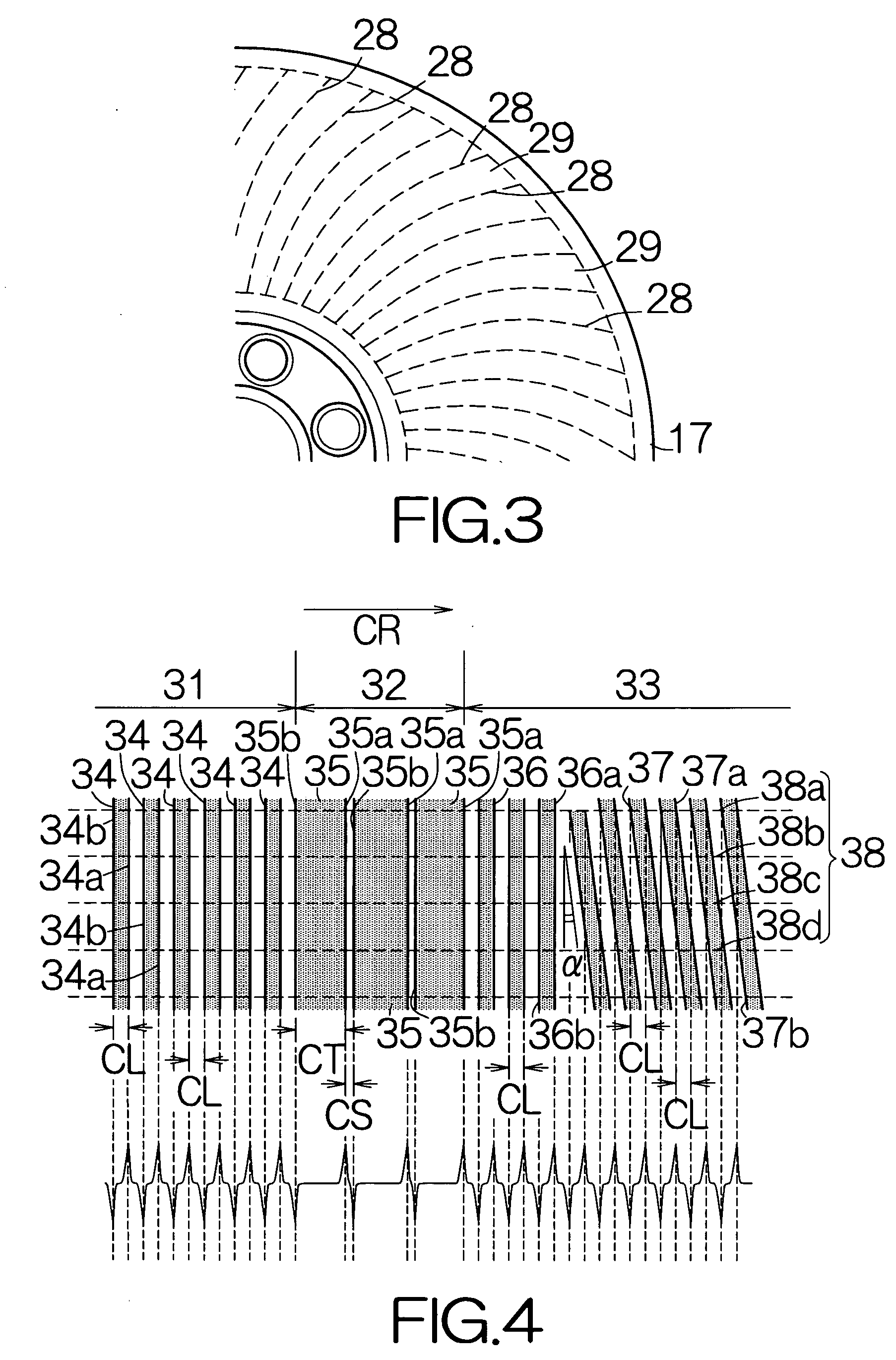
[0102] A HDD according to the present invention includes a magnetic recording disk 17a, in place of the magnetic recording disk 17, within the enclosure 12. As shown in FIG. 11, a preamble region 81, a servo mark region 82 and a servo data region 83 are, in this sequence from the upstream end, formed in the individual servo sector region 28 on the magnetic recording disk 17a, for example. The preamble and servo data regions 81, 83 have structures identical to that of the aforementioned preamble and servo data regions 31, 33. It should be noted that the magnetizations butt against each other at the upstream contours 34b of the individual synchronization magnetized stripes 34 in the preamble region 81. The positive magnetic poles are thus established along the upstream contours 34b of the synchronization magnetized stripes 34. On the other hand, the magnetizations are directed apart in the opposite directions at the downstream contours 34a of the synchronization magnetized stripes 34....

fourth embodiment

[0116] A HDD according to the present invention includes a magnetic recording disk 17c, in place of the magnetic recording disk 17, within the enclosure 12. As shown in FIG. 18, a preamble region 111, a servo mark region 112 and a servo data region 113 are, in this sequence from the upstream end, formed in the individual servo sector region 28 on the magnetic recording disk 17c, for example. The preamble and servo mark regions 111, 112 have structures identical to that of the aforementioned preamble and servo mark regions 31, 102.

[0117] The servo data region 113 includes a referential information region 114 dividing magnetizations by radii of the magnetic recording disk 17c. The reference magnetized stripes 36 are established within the referential information region 114 in the same manner as described above. A first positional information region 116 is formed downstream of the referential information region 114. The first positional information region 116 is designed to divide magn...


PUM

PropertyMeasurementUnit
magneticaaaaaaaaaa
magnetic fieldaaaaaaaaaa
radiusaaaaaaaaaa

Abstract

A master medium is utilized in a magnetic transfer apparatus. The master medium is superposed on a blank magnetic medium. A predetermined magnetic field is then applied to the master medium. The magnetic flux leaks from the master medium between adjacent magnetic pieces on the master medium. The leaked magnetic flux acts on the magnetic medium. The magnetization is accordingly established on the surface of the magnetic medium. Here, spaces can be reduced between the adjacent magnetic pieces on the master medium. Magnetization of a sufficient intensity can reliably be established on the magnetic medium.

Description

BACKGROUND OF THE INVENTION [0001] 1. Field of the Invention [0002] The present invention relates to a magnetic transfer apparatus designed to establish a servo region on a magnetic recording medium such as a magnetic disk, for example. The servo region serves to define recording tracks on the magnetic recording medium in a magnetic storage device such as a hard disk drive (HDD), for example. [0003] 2. Description of the Prior Art [0004] A preamble region, a servo mark region and a servo data region are in this sequence defined over a servo region on a magnetic recording disk. The preamble region includes alternate positive and negative magnetic poles equally spaced in the circumferential direction. The servo data region includes magnetic poles arranged in accordance with a predetermined pattern varying in the radial direction. A synchronization signal can be obtained in the HDD based on the magnetic information derived from the preamble region. A head is positioned right above a re...

Claims


Application Information

Patent Timeline
Patent Type & Authority Applications(United States)
IPC IPC(8): G11B5/55G11B5/596G11B5/86
CPCB82Y10/00G11B5/5526G11B5/865G11B5/743G11B5/59633
Inventor SUZUKI, HIROYUKIKOMORIYA, HITOSHINAKAMURA, YUTAKA
Owner TOSHIBA STORAGE DEVICE CORP
Why Eureka
Try Eureka