Ventilation system for electrical of electronic equipment
Active Publication Date: 2005-06-23
SAFRAN ELECTRONICS & DEFENSE
View PDF10 Cites 2 Cited by
Summary
Abstract
Description
Claims
Application Information
AI Technical Summary
This helps you quickly interpret patents by identifying the three key elements:
Problems solved by technology
Method used
Benefits of technology
Benefits of technology
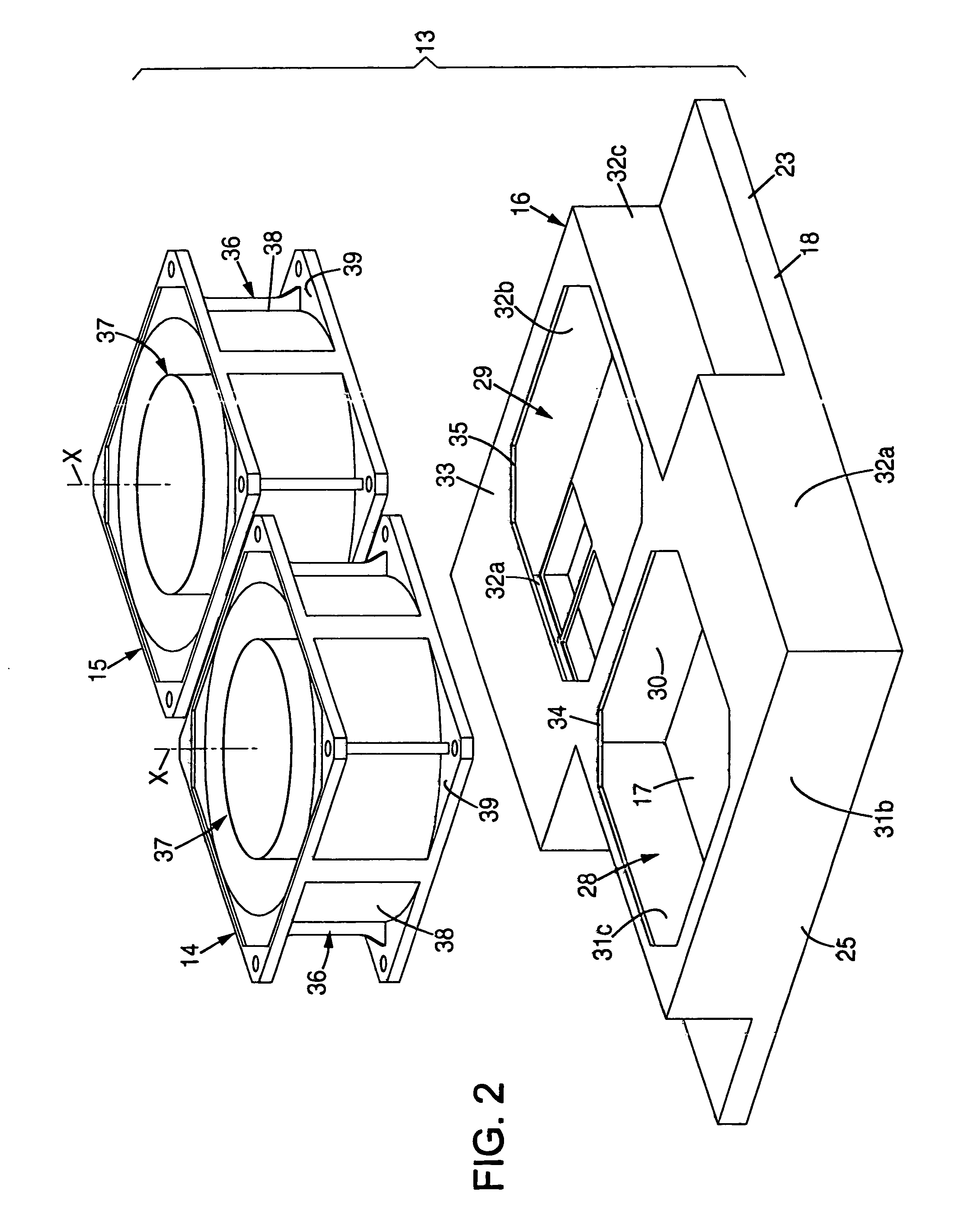
[0014] When both suction sources are in operation, i.e. when the ventilation system can operate at full capacity, air is sucked by both sources together. Since the air exhaust circuits are separated by the partitioning between the cavities, there is no risk of head loss being transferred from one circuit to the other. As a result, each of the suction sources operates independently, to the benefit of the overall reliability of the ventilation system.
[0027] Preferably, the cavities together cover the entire area of the air outlet so as to maximize the flow rate of air exhausted by the suction sources.
Problems solved by technology
When the equipment constitutes electronic circuits for automatic pilot control (or any other vital system), it will readily be understood that faulty ventilation, which would inevitably lead to the circuits overheating, could have consequences that are disastrous for the safety of the aircraft.
Nevertheless, when a breakdown occurs, the blower that has broken down then constitutes an obstacle to air flow, since as mentioned above, practically all of the air flow passes through the blower.
Method used
Image
Click on the blue label to locate the original text in one second.
Reading with bidirectional positioning of images and text.
Examples
first embodiment
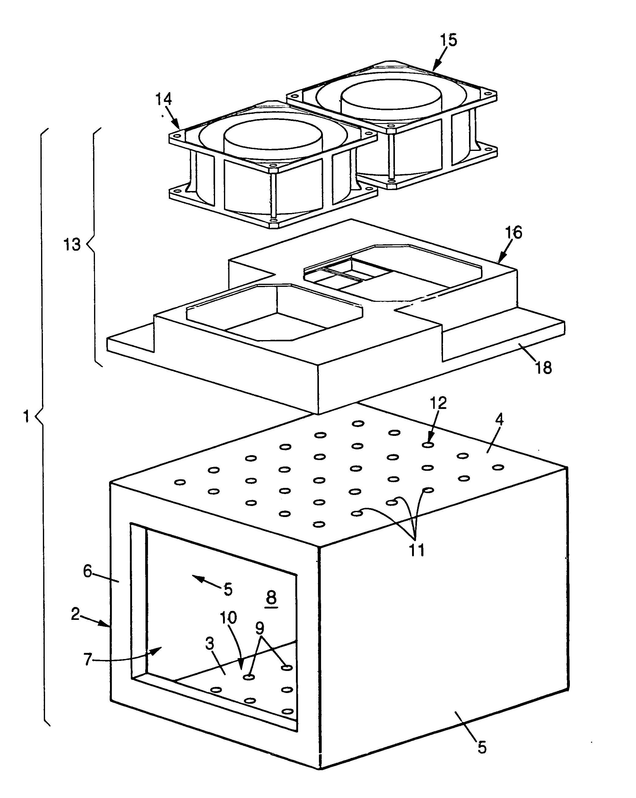
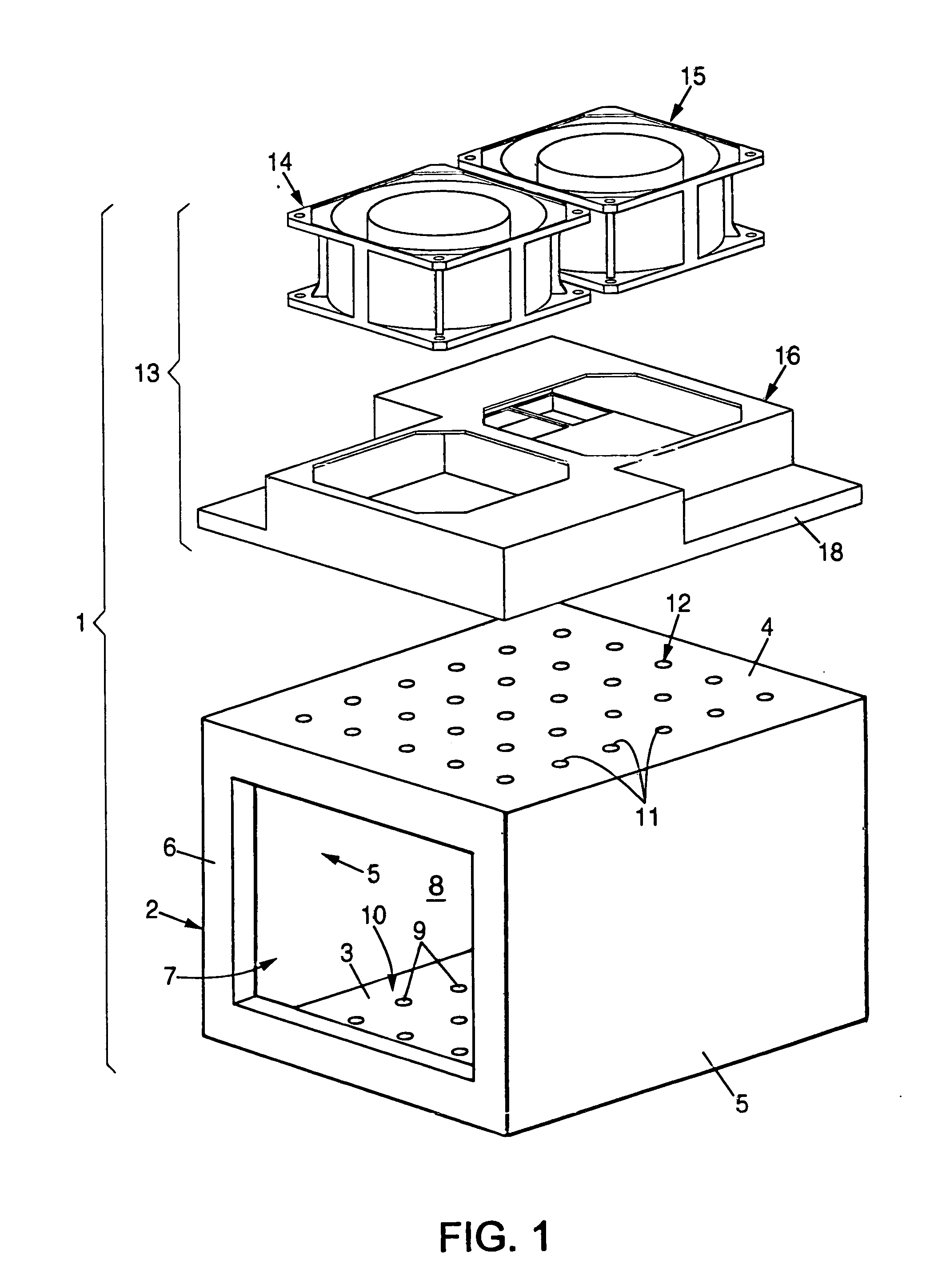
[0059] In a first embodiment, described with reference to FIGS. 3 to 5, the chest 16 has exactly two cavities 20 and 21 each in the shape of a comb, the two combs being interleaved one in the other and being separated by a continuous partition 22 extending along a crenellated pattern.
[0060] If the cavities 20 and 21 together cover the entire area of the air outlet 12, interleaving them enables each to take air from practically all of that area.
[0061] As a result, in the event of one of the air circuits, the primary circuit or secondary circuit, being inoperative due to a breakdown affecting one of the fans 14 and 15, the flow of air through the circuit that remains operational remains substantially uniform over the entire air outlet 12.
[0062] As a result, given the shape of each of the cavities 20 and 21, the suction caused by the fans 14 and 15 generates parallel upwardly-traveling sheets of air inside the enclosure 8 which penetrate into the perforations 9 and subsequently follo...
second embodiment
[0069] In a second embodiment, shown in FIGS. 6 to 9, the chest 16 has a plurality of primary cavities 20a, 20b, 20c, and 20d and a plurality of secondary cavities 21a, 21b, 21c, and 21d, in alternation, and separated in pairs by a plurality of parallel partitions 22a to 22g (which partitions are linear in the example shown) interconnecting two opposite edges 25 and 26 of the skirt 18.
[0070] A primary opening 43a, 43b, 43c, or 43d is formed through the wall 17 in the vicinity of one of the sides 23 for each of the primary cavities 20a, 20b, 20c, or 20d, and a secondary opening 44a, 44b, 44c, or 44d is formed in the vicinity of the opposite side for each of the secondary openings 21a, 21b, 21c, or 21d.
[0071] As a result, the primary cavities 20a to 20d are all in fluid flow communication with the primary chamber 28, while the secondary cavities 21a to 21d are all in fluid flow communication with the secondary chamber 29.
[0072] Given the symmetry and the uniformity of this configura...
PUM
Abstract
A ventilation system for electrical or electronic equipment installed in an enclosure of a box having an air inlet and an air outlet for establishing a flow of air through said enclosure, the ventilation system having at least two air suction sources, namely a primary source and a secondary source, and a chest for mounting on said box beside the air outlet, said chest defining at least two separate cavities, both for connection to the air outlet, namely a primary cavity connected to the primary source, and a secondary cavity connected to the secondary source, in such a manner as to create two separate air exhaust circuits from the outlet of the enclosure.
Description
[0001] The invention relates to cooling electrical or electronic equipment. [0002] More precisely, the invention relates to a ventilation system for electrical or electronic equipment installed in an enclosure of a box in which it is desired to establish a flow and then an extraction of air for cooling the equipment in operation. BACKGROUND OF THE INVENTION [0003] The inventors came across the problems associated with apparatus of this type in the field of aviation. In aircraft, where mechanical, and above all thermal, constraints are significant, it is essential to ensure that the system for ventilating electrical or electronic equipment is reliable so as to ensure that the equipment will be cooled under all circumstances. When the equipment constitutes electronic circuits for automatic pilot control (or any other vital system), it will readily be understood that faulty ventilation, which would inevitably lead to the circuits overheating, could have consequences that are disastrous...
Claims
Application Information
Patent Timeline
Application Date:The date an application was filed.
Publication Date:The date a patent or application was officially published.
First Publication Date:The earliest publication date of a patent with the same application number.
Issue Date:Publication date of the patent grant document.
PCT Entry Date:The Entry date of PCT National Phase.
Estimated Expiry Date:The statutory expiry date of a patent right according to the Patent Law, and it is the longest term of protection that the patent right can achieve without the termination of the patent right due to other reasons(Term extension factor has been taken into account ).
Invalid Date:Actual expiry date is based on effective date or publication date of legal transaction data of invalid patent.

