Miniature pump device and method

a miniature pump and pump body technology, applied in the field of fluid pumps, can solve the problems of reducing the size benefit of the miniature pump, reducing the frequency of small pumps, and requiring relative significant power, so as to minimize the power consumption of the pump during use, prevent leakage, and minimize turbulence and cavitation

Inactive Publication Date: 2008-10-23
JACOBSEN INNOVATIONS INC
View PDF20 Cites 0 Cited by
  • Summary
  • Abstract
  • Description
  • Claims
  • Application Information

AI Technical Summary

Benefits of technology

[0007]It has been recognized that it would be advantageous to develop a miniature pump device and method for pumping fluid. It has also been recognized that it would be advantageous to develop a miniature pump that has a stationary flexible seal that seals the moving parts of the pump within the fluid reservoir in order to minimize the power consumption of the pump during use, and prevent leakage. It has also been recognized that it would be advantageous to develop a miniature pump that reduces bubble formation in the fluid flow path to minimize turbulence and cavitation in the pumped fluid in order to maximize the flow rate from the pump.

Problems solved by technology

The moving seals in these types of pumps have presented problems in that relatively significant amounts of power are needed in order to overcome resistive frictional forces and move the seals.
Consequently, relatively large batteries or other power sources have been required to power these miniature pumps, thereby reducing the size benefit of the miniature pump.
Additionally, very small pumps typically operate at relatively high frequencies.
The rapid cycling of pistons, impellors, and seals can wear the seals and cause leakage of the pumped fluid out of the pump.
Moreover, high frequency cycling can cause cavitation, or the generation of gas bubbles, within the fluid flow path in the pump.
Bubbles can also be dangerous to patients when such pumps are used as drug delivery devices.

Method used


Image

  • Miniature pump device and method
  • Miniature pump device and method
  • Miniature pump device and method

Examples


Embodiment Construction

[0021]Reference will now be made to the exemplary embodiments illustrated in the drawings, and specific language will be used herein to describe the same. It will nevertheless be understood that no limitation of the scope of the invention is thereby intended. Alterations and further modifications of the inventive features illustrated herein, and additional applications of the principles of the inventions as illustrated herein, which would occur to one skilled in the relevant art and having possession of this disclosure, are to be considered within the scope of the invention.

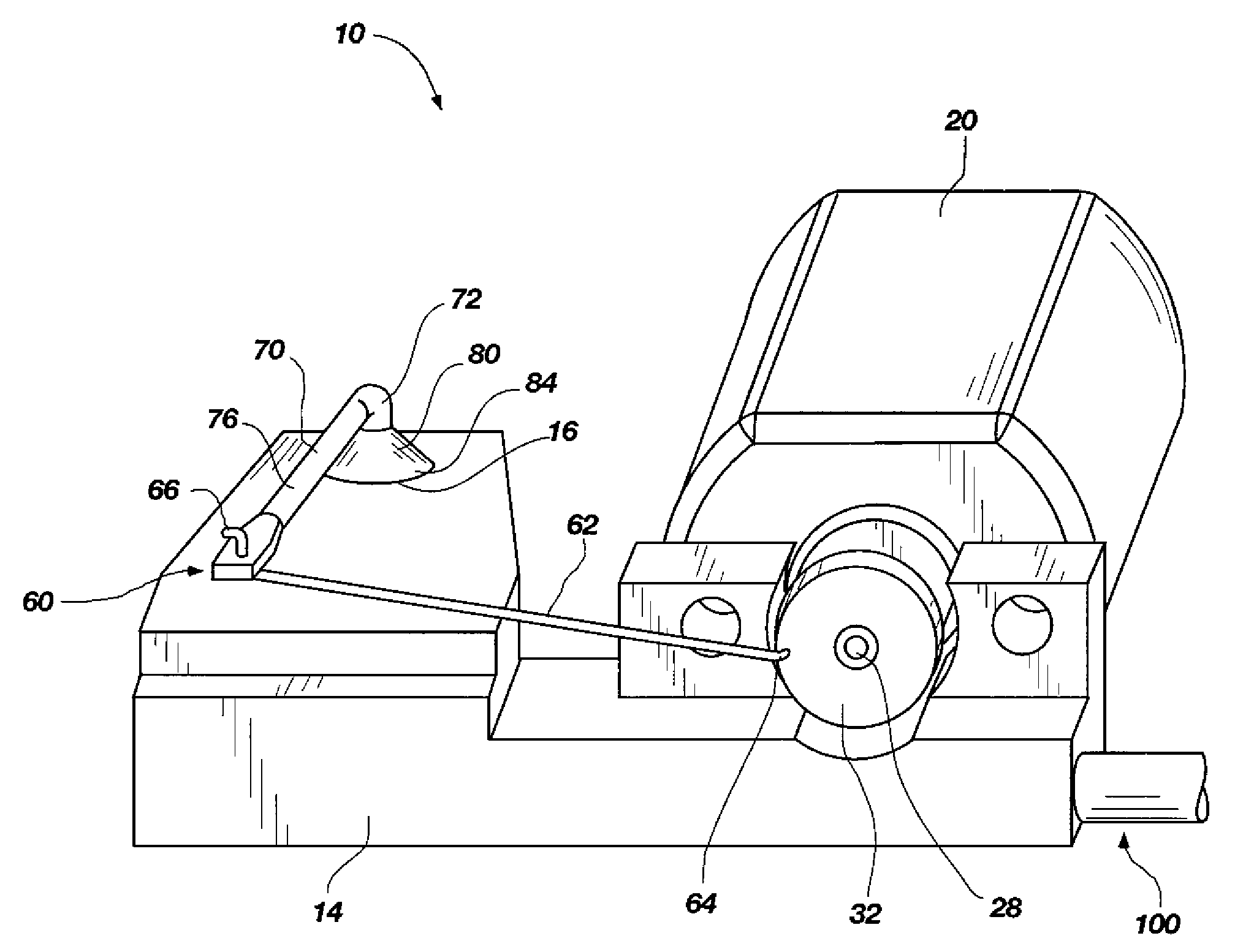
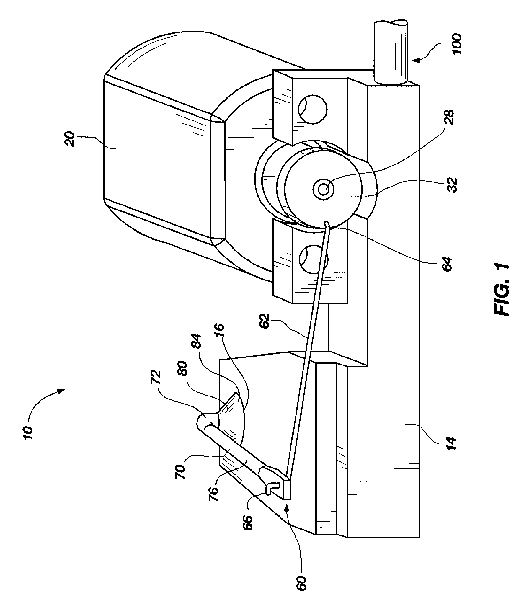
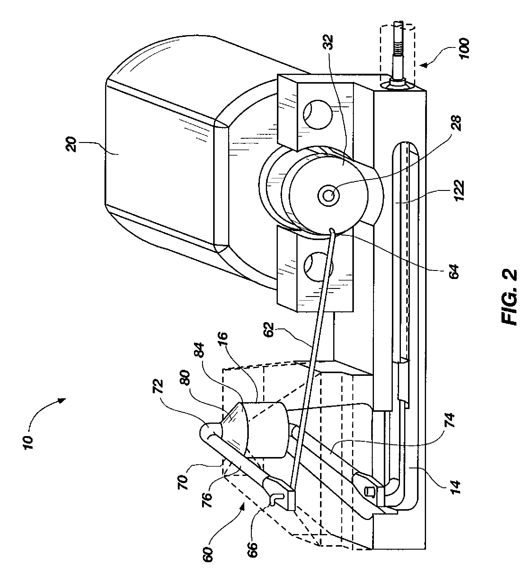
[0022]The present invention generally provides for a miniature pump that can be used as a drug delivery device, a miniature hydraulic pump, or the like. The pump has a stationary flexible seal to seal the moving parts of the pump within the fluid reservoir. The pump has a motor outside the fluid reservoir that drives a piston inside the fluid reservoir. A power transfer linkage extends from the motor to the pisto...


PUM


Abstract

A miniature pump device, with a fluid reservoir that can contain an intravenous drug, hydraulic fluid, or the like. The miniature pump has a motor disposed adjacent the fluid reservoir, and a piston disposed within the fluid reservoir. A power transfer linkage transfers power from the motor to the piston in the fluid reservoir, and a stationary flexible seal is coupled between the fluid reservoir and the power transfer linkage to seal a portion of the power transfer linkage within the fluid reservoir.

Description

[0001]This application claims the benefit of U.S. Provisional Application Ser. No. 60 / 923,334, filed Apr. 12, 2007, and entitled, “Miniature Pump Device and Method,” which is incorporated by reference in its entirety herein.BACKGROUND OF THE INVENTION[0002]1. Field of the Invention[0003]The present invention relates generally to fluid pumps, and more particularly to miniature jack or piston pumps.[0004]2. Related Art[0005]Miniature pumps have been used in a variety of applications such as drug delivery devices, miniature hydraulic systems, and the like. Some miniature pumps flex a diaphragm or use a dragging seal to create a vacuum to move fluid into and out of the pump. Other miniature pumps, such as piston pumps, have to rotate or slide a seal in order to push or impel fluid through the pump. The moving seals in these types of pumps have presented problems in that relatively significant amounts of power are needed in order to overcome resistive frictional forces and move the seals...

Claims


Application Information

Patent Timeline
Patent Type & Authority Applications(United States)
IPC IPC(8): A61M1/00
CPCA61M5/14216F04B17/03
Inventor JACOBSEN, STEPHEN C.OLSEN, SHANE E.
Owner JACOBSEN INNOVATIONS INC
Why Eureka
Try Eureka