Fluid control device

a control device and flue gas technology, applied in the field of flue gas control devices, can solve the problems of excessive infusion of medical solutions, and misoperation of medical staff, so as to reduce the risk and maximize the flow rate

Active Publication Date: 2020-10-20
MURATA MFG CO LTD
View PDF9 Cites 0 Cited by
  • Summary
  • Abstract
  • Description
  • Claims
  • Application Information

AI Technical Summary

Benefits of technology

[0007]In consideration of the above-described problems, the present disclosure provides a fluid control device capable of reducing a risk that a tube is released from a pressed state and a flow rate is maximized in spite of being not intended by a medical staff.
[0009]With the features described above, since the tube inserted into the tube insertion portion is fixedly held in the tube insertion portion by the fixing member, the tube is hard to displace from the tube insertion portion even with application of external force. Furthermore, since the tube inserted into the tube insertion portion is automatically pressed by the pressing member, the pressing on the tube is maintained unless an operation to stop the pressing is performed. As a result, a risk of the tube coming into the free flow state can be reduced.
[0015]Moreover, the second resilient member is deformed even when the operating member receives the operation in a state where the fixing member is restricted by the pressing member from moving to the tube fixing position. It is hence possible to prevent the tube from being removed from the tube insertion portion with the fixing member moved forcedly, and to avoid damages of the fixing member, the operating member, the pressing member, the actuator, etc.
[0017]In the fluid control device, the pressing on the tube by the pressing member needs to be stopped in order to remove the tube from the tube insertion portion. However, when the amount of the drops dripping in the drip unit increases (including an increase in the number of the drops and an increase in drop size) in a process where pressing strength applied to the tube by the pressing member gradually decreases during an operation of reducing the pressing on the tube by the pressing member or after the pressing member and the infusion tube have been moved away from each other, there is a risk that the tube may come into the free flow state if the pressing on the tube is stopped in such a state. The risk of the tube coming into the free flow state can be reduced by, as described above, intensifying or resuming the pressing on the tube when the amount of the drops dripping in the drop unit increases.
[0020]According to the present disclosure, since the tube inserted into the tube insertion portion is fixedly held by the fixing member and is pressed by the pressing member, it is possible to reduce the risk that the tube is released from a pressed state and a flow rate is maximized in spite of being not intended by a medical staff.

Problems solved by technology

In the case of controlling the flow rate through the infusion tube with the electrical clamp, if the infusion tube is detached from the electrical clamp, there would be a risk that the flow rate through the infusion tube comes into a maximized state (called also a “free flow state”) and the medical solution is infused excessively.
Furthermore, combined use of the manual clamp and the electrical clamp may cause another risk that a medical staff mistakes operating procedures for the drip infusion and the infusion tube comes into the free flow state.

Method used


Image

  • Fluid control device
  • Fluid control device
  • Fluid control device

Examples


first embodiment

[0035]A fluid control device according to the present disclosure will be described below in connection with the case where the fluid control device is applied to a drip set. In the following description, “up” and “down” are defined as denoting “up” and “down” in postures of individual components during drip infusion.

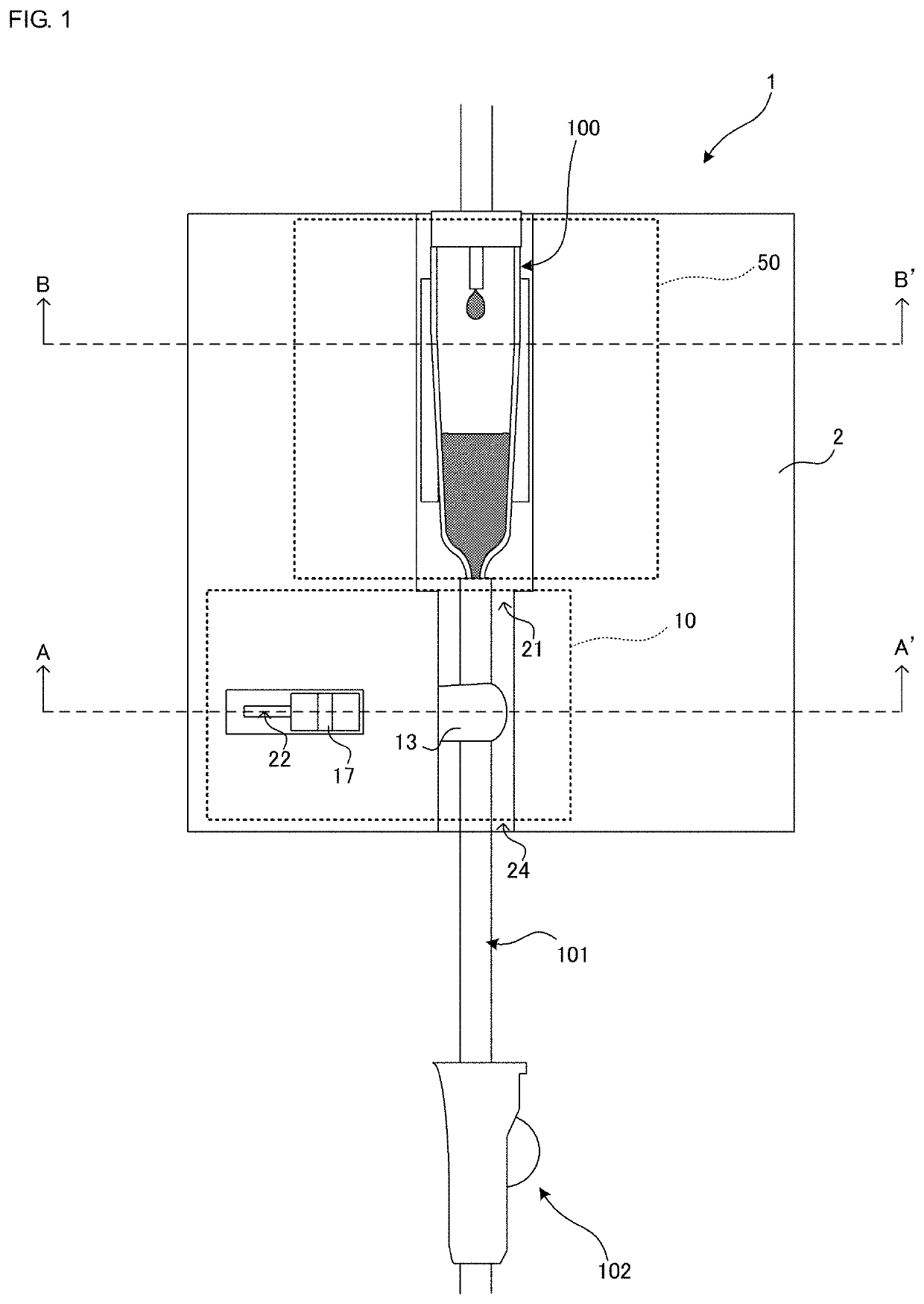
[0036]FIG. 1 is a schematic view of a drip set using a fluid control device 1 according to a first embodiment of the present disclosure. The fluid control device 1 illustrated in FIG. 1 constitutes part of a drip set and is used in combination with a drip chamber 100, an infusion tube 101, and a manual clamp 102.

[0037]Not-illustrated needles are attached to both ends of the infusion tube 101. The needle at the upper end side of the infusion tube 101 is pierced into a medical solution bag not illustrated. The needle at the lower end side of the infusion tube 101 is pierced, for example, into the skin of a patient not illustrated. The drip chamber 100 is disposed intermedi...

second embodiment

[0083]The fluid control device includes an electrical clamp 10E.

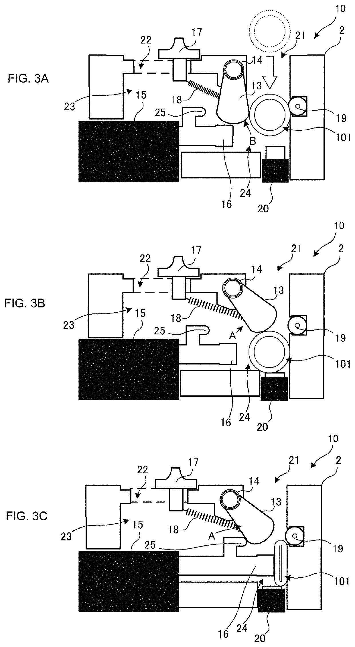
[0084]FIGS. 6A-6C are schematic views illustrating a cross-section of the electrical clamp 10E.

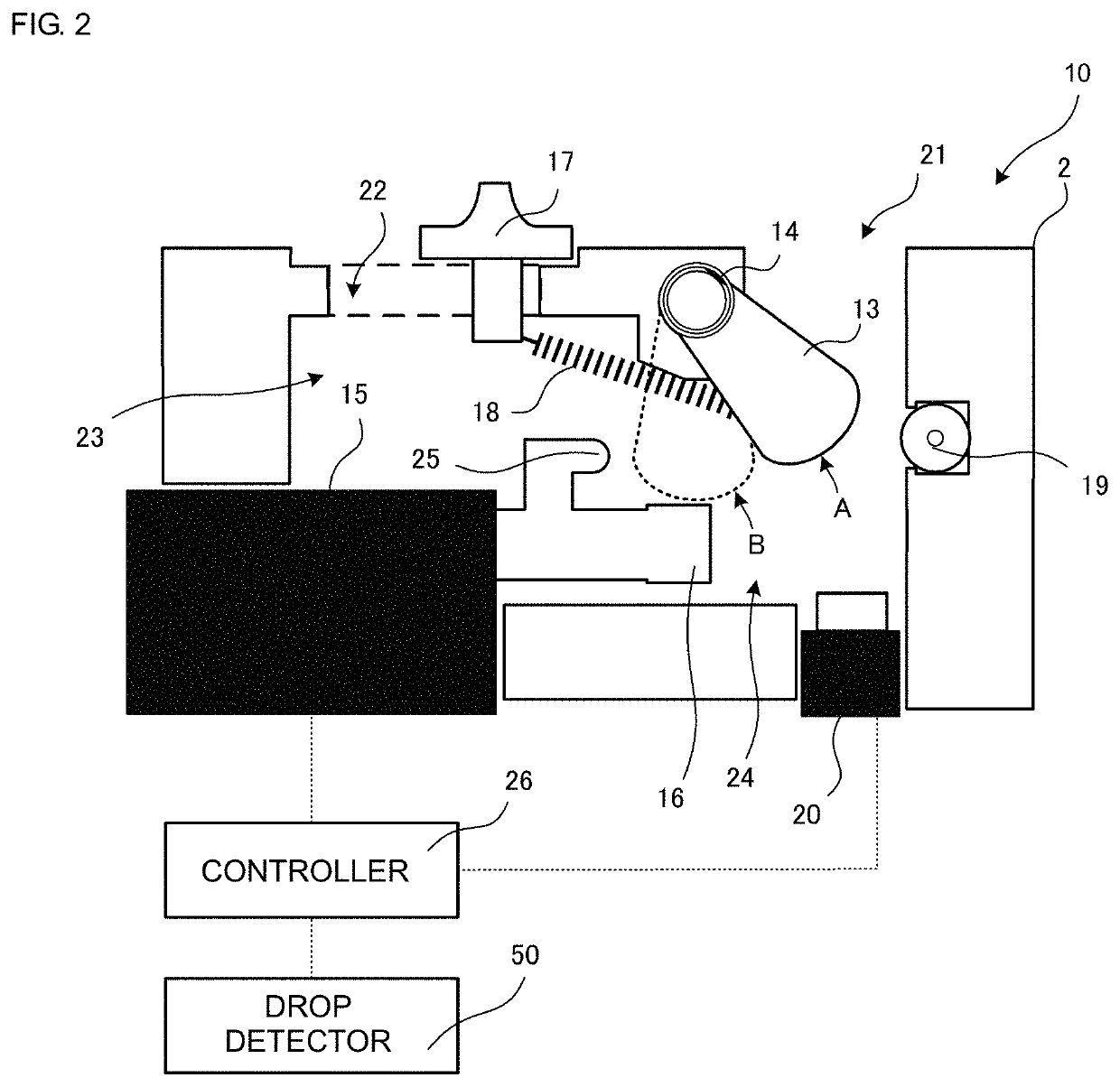
[0085]The electrical clamp 10E includes a casing 2, a plunger (fixing member) 13E, a compression spring (first resilient member) 14E, an actuator 15, a pressing member 16, a slider (operating member) 17, a tension spring (second resilient member) 18, a roller (rolling element) 19, a switch 20, and a not-illustrated controller 26.

[0086]The plunger 13E corresponds to the fixing member in the present disclosure. One end portion of the plunger 13E is reciprocally movable, as with the pressing member 16, between a state retracted into a casing chamber 23 and a state projecting into a tube insertion portion 24. The other end of the plunger 13E is attached to the compression spring 14E and is fixedly fitted, together with the compression spring 14E, to a plunger fixing portion 30E provided in the casing 2. The compression spring 14E...

third embodiment

[0092]In consideration of the above point, the third embodiment employs a mechanism for preventing the drip chamber 100 from being removed during the drip infusion.

[0093]FIG. 7 is a schematic view of a drop detector 50F.

[0094]The drop detector 50F is to hold the above-mentioned drip chamber 100 and to detect the amount of the drops with a not-illustrated optical sensor, for example. The drop detector 50F includes a drip chamber gripper 51F. The drip chamber gripper 51F is in the form of a leaf spring curved to follow the drip chamber 100, and it has a diameter comparable to or slightly smaller than that of the drip chamber 100. Thus, the drip chamber gripper 51F in the form of a leaf spring is constituted to be able to hold the drip chamber 100 between both ends thereof with both the ends deformed in swinging motions such that the drip chamber 100 can be detachably attached in place.

[0095]The drop detector 50F further includes a drip chamber stopper 52F for restricting deformation o...


PUM


Abstract

A fluid control device includes a tube insertion portion formed in a casing, a fixing member that fixedly holds, in the tube insertion portion, a tube inserted into the tube insertion portion, a pressing member driven by an actuator to press the tube within the tube insertion portion, and a controller that controls the actuator for the pressing member, wherein the controller controls the pressing member to start pressing on the tube after the fixing member has fixedly hold the tube in the tube insertion portion.

Description

[0001]This is a continuation of International Application No. PCT / JP2016 / 074577 filed on Aug. 24, 2016, which claims priority from Japanese Patent Application No. 2016-106871 filed on May 28, 2016 and from Japanese Patent Application No. 2015-165544 filed on Aug. 25, 2015. The contents of these applications are incorporated herein by reference in their entireties.BACKGROUNDTechnical Field[0002]The present disclosure relates to a fluid control device that is attached to a tube through which a fluid flows, and that controls a flow rate of the fluid.[0003]A drip set for a drip infusion generally includes an infusion tube through which a medical solution is fed from an infusion bag, a drip chamber enabling the medical solution in the infusion tube to be visually recognized, and a manual clamp for adjusting a flow rate of the medical solution flowing through the infusion tube. The manual clamp is disposed to grip the infusion tube from the outside, and adjusts the flow rate of the medica...

Claims


Application Information

Patent Timeline
Patent Type & Authority Patents(United States)
IPC IPC(8): A61M5/14A61M5/172A61M5/168A61M39/28
CPCA61M39/281A61M5/172A61M5/1411A61M5/16877A61M5/16804A61M2205/3306A61M2205/3561A61M2205/14
Inventor HIRATA, ATSUHIKOAMAGAI, YOSHIHIDEKONDO, NOBUHIROHANE, YOSHITAKA
Owner MURATA MFG CO LTD
Why Eureka
Try Eureka