Rotorcraft equipped with an aerodynamic device having a fairing provided with an air inlet

a technology of aerodynamic devices and rotorcraft, which is applied in the field of rotorcraft, can solve the problems of non-negligible capture drag, high cost, and high cost, and achieves the effects of reducing the risk of vibration on the tail boom, and improving the safety of pilots

Active Publication Date: 2020-11-05
EUROCOPTER
View PDF0 Cites 0 Cited by
  • Summary
  • Abstract
  • Description
  • Claims
  • Application Information

AI Technical Summary

Benefits of technology

[0025]In addition, unlike with a grid having openings that are uniformly distributed and that are generally of square or rectangular shape, it is possible, by freely changing the size, positioning, shape and/or number of perforations in a perforated plate, to adapt the characteristics relating to the f

Problems solved by technology

In addition, the mouth of the air inlet situated on the fuselage is particularly complex to dimension.
However, during a forward flight phase, a large mouth can generate uncontrolled delivery of cool air, and can cause non-negligible capture drag with a risk of vibration on the tail boom and/or poor cooling of a heat exchanger.
Conversely, while the rotorcraft is in a hovering flight phase, a mouth of small dimensions generates h

Method used


Image

  • Rotorcraft equipped with an aerodynamic device having a fairing provided with an air inlet
  • Rotorcraft equipped with an aerodynamic device having a fairing provided with an air inlet

Examples


Embodiment Construction

[0062]Elements present in more than one of the figures may be given the same references in each of them.

[0063]As indicated above, the invention relates to a rotorcraft having at least one rotor that at least participates in providing lift, and may also participate in providing propulsion, for the rotorcraft in the air.

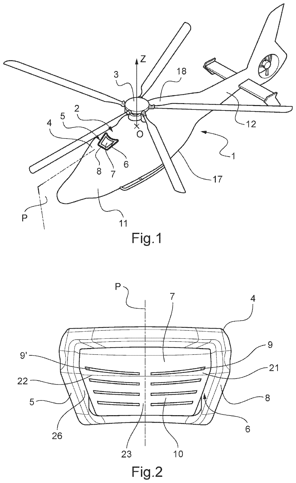
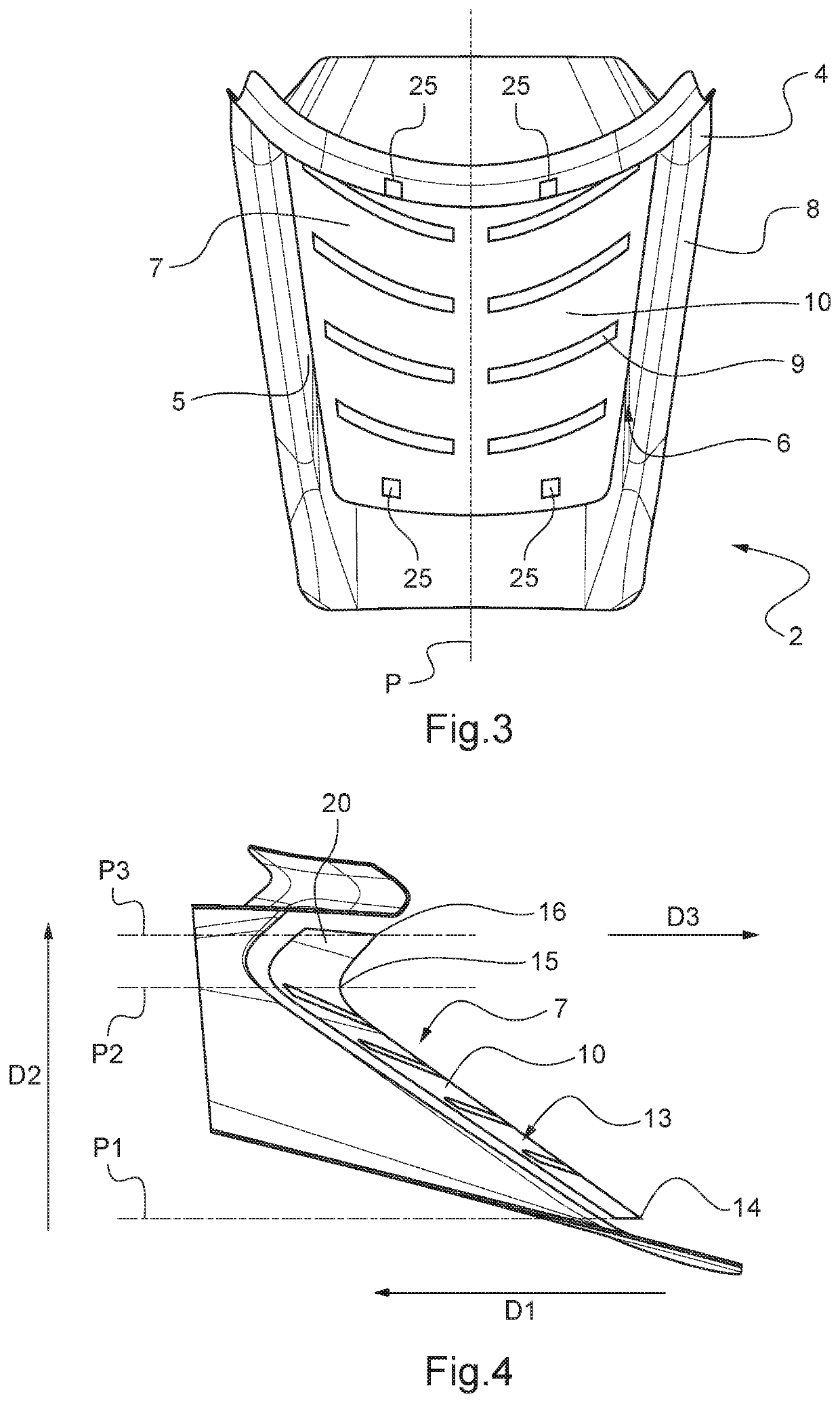
[0064]As shown in FIG. 1, such a rotorcraft 1 has an aerodynamic device 2 arranged below the rotor 3 that rotates about an axis of rotation OZ. Furthermore, the aerodynamic device 2 has a fairing 4 that is provided with at least one air inlet 5 so as to make it possible for a stream of cool air to flow from a region situated outside the rotorcraft 1 to another region that is situated inside the rotorcraft 1.

[0065]The air inlet 5 has a mouth 6 delimited by an outer peripheral portion 8 of the fairing 4. Furthermore, the aerodynamic device 2 includes a perforated plate 7 arranged at the mouth 6.

[0066]In addition, the perforated plate 7 may extend laterally on either side...


PUM


Abstract

A rotorcraft having an aerodynamic device arranged below a rotor, which rotor participates at least in providing lift for the rotorcraft, the rotor being mounted to rotate about an axis of rotation, the aerodynamic device having a fairing provided with at least one air inlet for enabling a stream of cool air to flow from a region that is situated outside the rotorcraft to another region that is situated inside, the air inlet being delimited by an outer peripheral portion of the fairing. In accordance with the invention, the aerodynamic device has a perforated plate provided with at least one perforation, the perforation being suitable for allowing the stream of cool air to pass through it, the perforated plate having at least one main portion shaped to match an outer shape of the outer peripheral portion of said fairing.

Description

CROSS-REFERENCE TO RELATED APPLICATIONS[0001]This application claims priority to European patent application No. FR 19 04542 filed on Apr. 30, 2019, the disclosure of which is incorporated in its entirety by reference herein.BACKGROUND OF THE INVENTION(1) Field of the Invention[0002]The present invention relates to the field of aviation and more particularly to the field of rotorcraft. Such aircraft have at least one rotor equipped with blades making it possible to provide lift for an aircraft, or indeed propulsion for the aircraft, in the air.(2) Description of Related Art[0003]More precisely, the invention applies to the field of aerodynamic devices that are arranged on the fuselage or outer skin of such a rotorcraft. Such an aerodynamic device may have a fairing making it possible, for example, to protect an engine and / or a main gearbox of a rotorcraft.[0004]Furthermore, such fairings may be provided with one or more cool air inlets making it possible, for example, for outside ai...

Claims


Application Information

Patent Timeline
IPC IPC(8): B64D29/04B64C21/02
CPCB64D33/08B64C27/04B64D29/04B64C21/02B64D29/00B64D33/02B64D2033/024
Inventor SERR, CHRISTOPHEHONNORAT, OLIVIERCOQUILLAT, JEAN-CHRISTOPHE
Owner EUROCOPTER
Why Eureka
Try Eureka