

Illumination device
a technology of a slit-type device and a slit-type body, which is applied in the direction of mechanical equipment, lighting and heating equipment, instruments, etc., can solve the problems of new challenges and achieve the effect of improving spatial or spectral uniformity
- Summary
- Abstract
- Description
- Claims
- Application Information
AI Technical Summary
Benefits of technology
Problems solved by technology
Method used
Image

Examples
Embodiment Construction
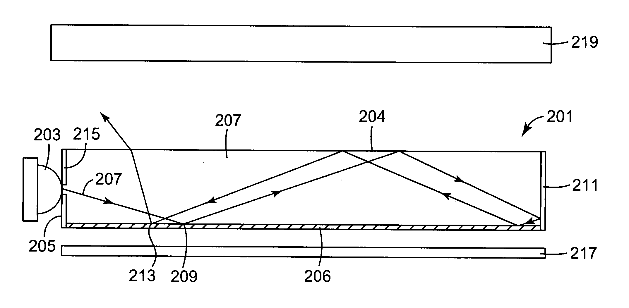
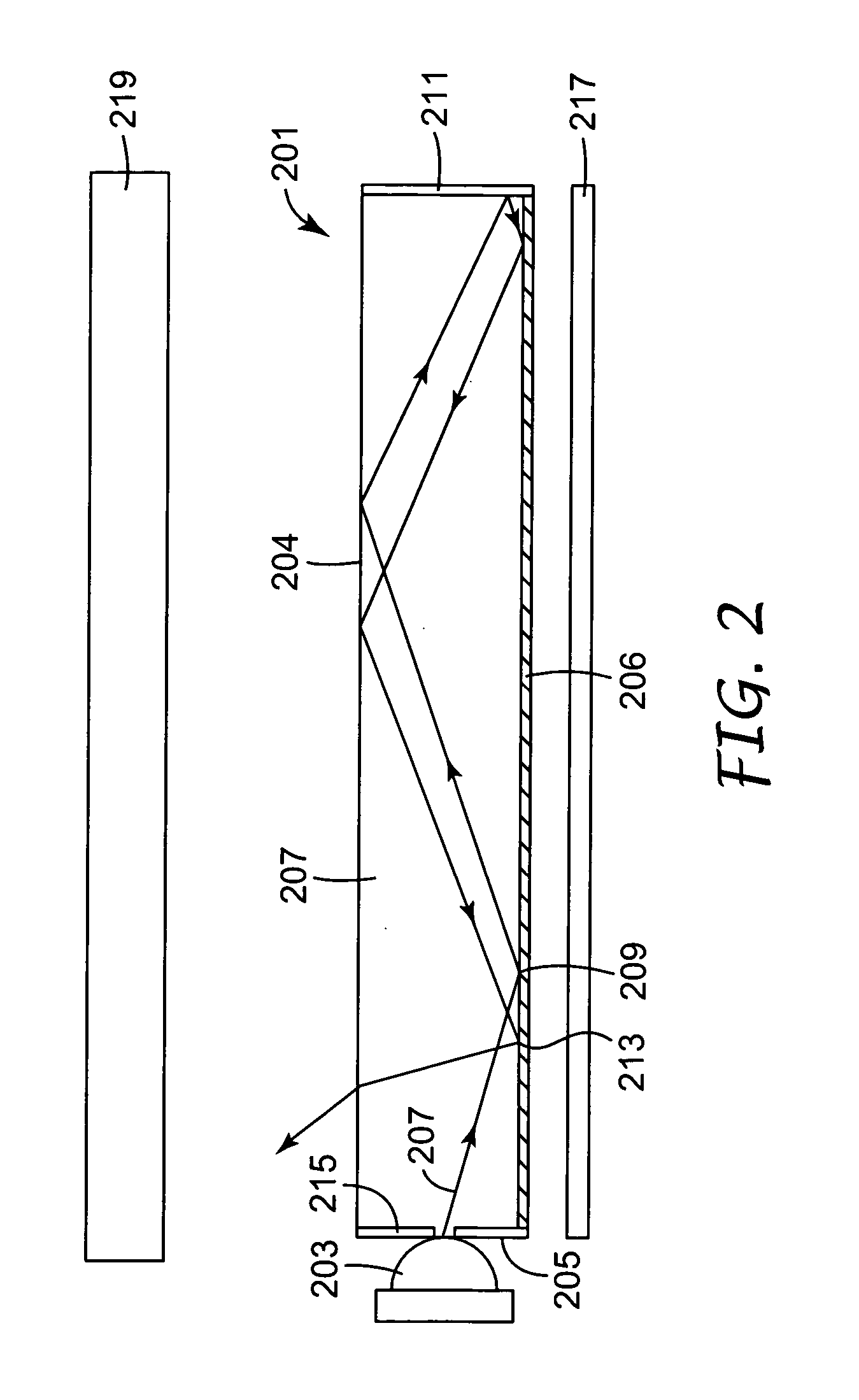
[0034] The present application is directed generally to lighting systems. More particularly, the present invention is directed to an improved illumination system. The illumination system has the ability to provide uniform lighting over a surface area. Light from multiple light sources such as LEDs can be mixed in order to improve lighting uniformity or to mix colors from different colored light sources to produce a desired illumination of blended colors, e.g., white.
[0035] In accordance with one aspect of the present invention, a light guide is provided which includes extracting structures provided on a surface of the light guide. The light guide and the structures cooperatively interact to improve the uniformity (and mixing) of light in and extracted from the light guide. In accordance with one particular embodiment of the invention, the lighting system includes an input area through which light is introduced into a light guide. Light introduced into the light guide propagates bet...
PUM
 Abstract
Description
Claims
Application Information