Method of controlling thermal waves in reactive multilayer joining and resulting product

US20050136270A1Inactive Publication Date: 2005-06-23REACTIVE NANOTECH

Image

  • Method of controlling thermal waves in reactive multilayer joining and resulting product
  • Method of controlling thermal waves in reactive multilayer joining and resulting product
  • Method of controlling thermal waves in reactive multilayer joining and resulting product

Examples


Embodiment Construction

[0003] 1. Field of the Invention

[0004] The invention is directed toward methods of selecting components for a reactive joining process and their respective configurations based on simulated data so as to produce a joint with desired properties. The invention is also directed towards joints produced by implementing such methods.

[0005] 2. Background of the Invention

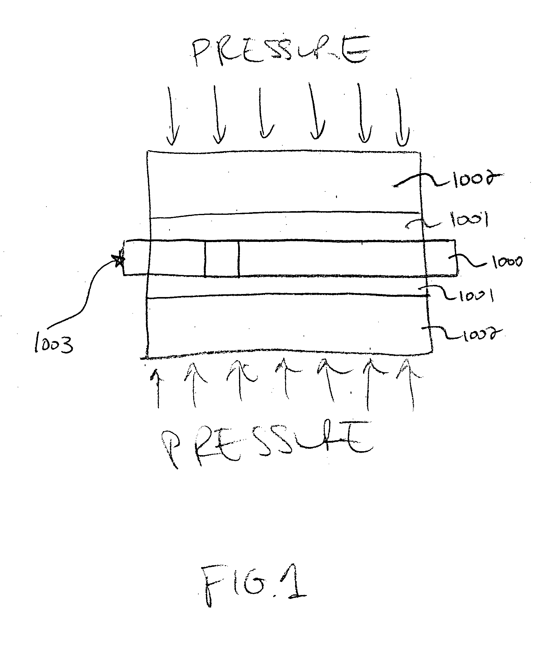
[0006] Reactive multilayer joining is a particularly advantageous process for soldering, brazing or welding materials. A typical reactive multilayer joining process is schematically illustrated in FIG. 1. This room-temperature bonding process is based on sandwiching under pressure a reactive multilayer foil 1000 between two layers of a fusible material 1001 and the two components 1002 to be joined, and then igniting the foil 1000, for example, using a spark 1003. A self-propagating reaction is thus initiated which results in a rapid rise in the temperature of the reactive foil 1000. The heat released by the reaction melt...


PUM

PropertyMeasurementUnit
Temperatureaaaaaaaaaa
Lengthaaaaaaaaaa
Thicknessaaaaaaaaaa

Abstract

An embodiment of the invention includes a method of simulating a behavior of an energy distribution within a soldered or brazed assembly to predict various physical parameters of the assembly. The assembly typically includes a reactive multilayer material. The method comprises the steps of providing an energy evolution equation having an energy source term associated with a self-propagating reaction that originates within the reactive multilayer material. The method also includes the steps of discretizing the energy evolution equation, and determining the behavior of the energy distribution in the assembly by integrating the discretized energy evolution equation using other parameters associated with the assembly.

Description

CROSS-REFERENCE TO RELATED APPLICATION [0001] This application claims the benefits of priority under 35 U.S.C. §119(e) to U.S. Provisional Patent Application No. 60 / 469,841, the entirety of which is incorporated herein by reference.STATEMENT REGARDING FEDERALLY SPONSORED RESEARCH [0002] This invention was made with U.S. Government support under National Science Foundation Award Nos. DMI-0115238, DMI-0215109, and U.S. Army Contract No. DAAD17-03-C-0052. The U.S. Government has certain rights in this invention.DESCRIPTION OF THE INVENTION [0003] 1. Field of the Invention [0004] The invention is directed toward methods of selecting components for a reactive joining process and their respective configurations based on simulated data so as to produce a joint with desired properties. The invention is also directed towards joints produced by implementing such methods. [0005] 2. Background of the Invention [0006] Reactive multilayer joining is a particularly advantageous process for solderi...

Claims


Application Information

Patent Timeline
23 Jun 2005
Publication
US20050136270A1
IPC
B23K1/00; B23K1/19; B23K31/02; B23K31/12; B23K35/00; B23K35/02; B23K35/34; C06B45/14; G05B17/02
CPC
B23K1/0016; B23K31/02; B23K31/12; B23K35/001; B23K35/0238; B23K35/34; Y10T428/12535; B23K2203/04
Inventors
BESNOIN, ETIENNE; WANG, JIAPING