Liposuction/tubing coupling for providing rotational movement

a technology of liposuction and rotational movement, which is applied in the direction of catheters, intravenous devices, other medical devices, etc., can solve the problems of tumescent liposuction having the drawback of being laborious, and the liposuction procedure will not be properly performed

Inactive Publication Date: 2005-06-23
AZAR KOUROS
View PDF32 Cites 22 Cited by
  • Summary
  • Abstract
  • Description
  • Claims
  • Application Information

AI Technical Summary

Benefits of technology

[0007] The present invention specifically addresses and alleviates the above-identified deficiencies in the art. In this regard, the present invention is directed to a fitting or coupling interposeable between a liposuction cannula and suction tubing coupled therewith that is operative to provide independent rotational movement of either the liposuction cannula and / or suction tubing about a common axis while maintaining such elements in an operatively conjoined configuration.

Problems solved by technology

Over time, within the targeted fat compartment, the series of tunnels formed collapse and ultimately cause the compartment to assume a desired contour.
Despite the popularity of such procedure, tumescent liposuction does have the drawback of being labor intensive for the surgeon performing the operation.
Otherwise the liposuction procedure will not be properly performed.
While advances have been made with respect to automated liposuction cannula deployment, such as power-assisted cannula produced by MicroAire Surgical Instruments, LLC, of Charlottesville, Va., the same still do not address the issue of the continuous twisting and kinking of the suction tubing that is rigidly connected to the liposuction cannula.

Method used


Image

  • Liposuction/tubing coupling for providing rotational movement
  • Liposuction/tubing coupling for providing rotational movement

Examples


Embodiment Construction

[0015] The detailed description set forth below is intended as a description of the presently preferred embodiment of the invention, and is not intended to represent the only form in which the present invention may be constructed or utilized. The description sets forth the functions and sequences of steps for constructing and operating the invention. It is to be understood, however, that the same or equivalent functions and sequences may be accomplished by different embodiments and that they are also intended to be encompassed within the scope of the invention.

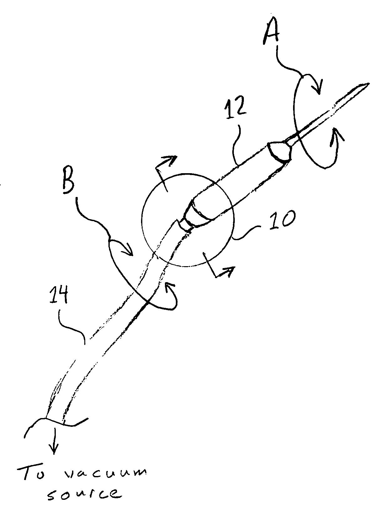
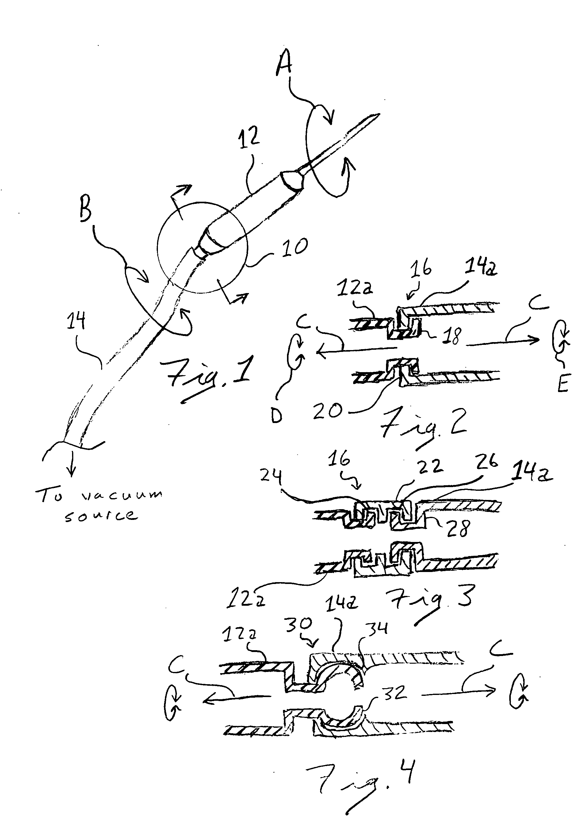
[0016] Referring now to the drawings, and initially to FIG. 1, there is perspectively illustrated a liposuction cannula 12 having a section of suction tubing 14 operatively connected thereto and extending therefrom. At the juncture between the liposuction cannula and suction tubing is an interface 10 that is operative to enable the liposuction and cannula and / or suction tubing to rotate freely relative one another, as reflect...


PUM


Abstract

A liposuction cannula/suction tubing coupling is disclosed that enables the tubing to rotate freely about the juncture at which the tubing is coupled to the cannula. Such coupling may be formed as a separate fitting that is interconnected intermediate the liposuction cannula and the suction tubing, or integrally formed as part of the liposuction cannula, on one hand, or on the suction tubing, on the other hand.

Description

CROSS-REFERENCE TO RELATED APPLICATIONS [0001] Not Applicable STATEMENT RE: FEDERALLY SPONSORED RESEARCH / DEVELOPMENT [0002] Not Applicable BACKGROUND OF THE INVENTION [0003] Surgical procedures involving lipoplasty are well-known in the art. Perhaps the most well-known and extensively performed of such procedures is tumescent liposuction, which employs a large volume of fluid, generally comprised of a very dilute epinephrine solution and a dilute anesthetic solution, that is infiltrated into a target fat compartment to produce swelling and firmness therein. In this regard, such fluid is operative to maintain the fat in a tumescent state while at the same time producing vasoconstriction and localized anesthesia. While the fat is maintained in such tumescent state, a liposuction cannula is systematically inserted into the fat compartment in a series of elongate paths. Such cannula, which is connected to a suction device, namely, surgical tubing operatively connected with a vacuum or s...

Claims


Application Information

Patent Timeline
Patent Type & Authority Applications(United States)
IPC IPC(8): A61M1/00
CPCA61M1/008A61M1/0086A61M2202/08A61M1/842A61M1/86
Inventor AZAR, KOUROS
Owner AZAR KOUROS
Why Eureka
Try Eureka