Liposculpting Device

a technology of a sculpting device and a splint, which is applied in the field of apparatus, can solve the problems of fatty tissue damage, traumatic procedure with a risk of complications, excessive bleeding, etc., and achieve the effect of convenient operation and inexpensive manufacturing

Active Publication Date: 2008-05-01
ADAMSON CHRISTOPHER D
View PDF17 Cites 20 Cited by
  • Summary
  • Abstract
  • Description
  • Claims
  • Application Information

AI Technical Summary

Benefits of technology

[0017] Another important object is to accomplish adipose removal with a simple hand-held device that is easy to operate and inexpensive to manufacture.

Problems solved by technology

Traditional liposuction is a generally safe but possibly traumatic procedure with a risk of complications.
As the cannula is moved through the tissue region, it may damage nerves and / or blood vessels, as well as fatty tissue.
Complications include excessive bleeding and a risk of morbidity or mortality.
Another potential problem with liposuction is lack of uniformity of the patient's final shape due to irregular removal of fatty tissue, with subsequent contour deformities.
One shortcoming of UAL techniques is that the transducer may become quite hot during its use.
This may result in damage or destruction of tissues adjacent to the target region by overheating or melting.
Treatment may also be limited to direct contact between the transducer and the adipose tissue, which may result in non-uniform destruction of fat cells in the target region.
Additionally, it may be difficult to achieve the desired effect due to limitations in the process.

Method used


Image

  • Liposculpting Device
  • Liposculpting Device
  • Liposculpting Device

Examples


first embodiment

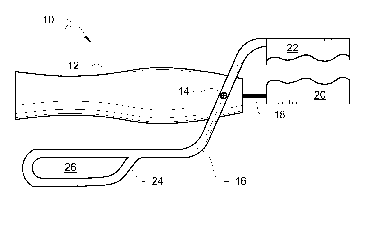
[0030] In this first embodiment, the opposing surfaces of the plates are sinusoidal in configured when viewed in side elevation. The crest of one sine wave is opposed to the valley of its opposed sine wave so that plates 20 and 22 can be brought close together.

[0031] Although sinusoidal plates are preferred, this invention is not limited to opposing plates having confronting surfaces of that shape because the invention will also work with other shapes, including flat surfaces. The plates may be generally textured with a regular or irregular pattern. The confronting surface of each plate may include other geometrical configurations such as rectangles, hemispheres, waffle patterns and so on. The sinusoidal shape is preferred because it creates repeated increased force application to a particular area of fat as the crests of the two opposing sine wave patterns advantageously pass each other in a reciprocating manner as disclosed hereinafter.

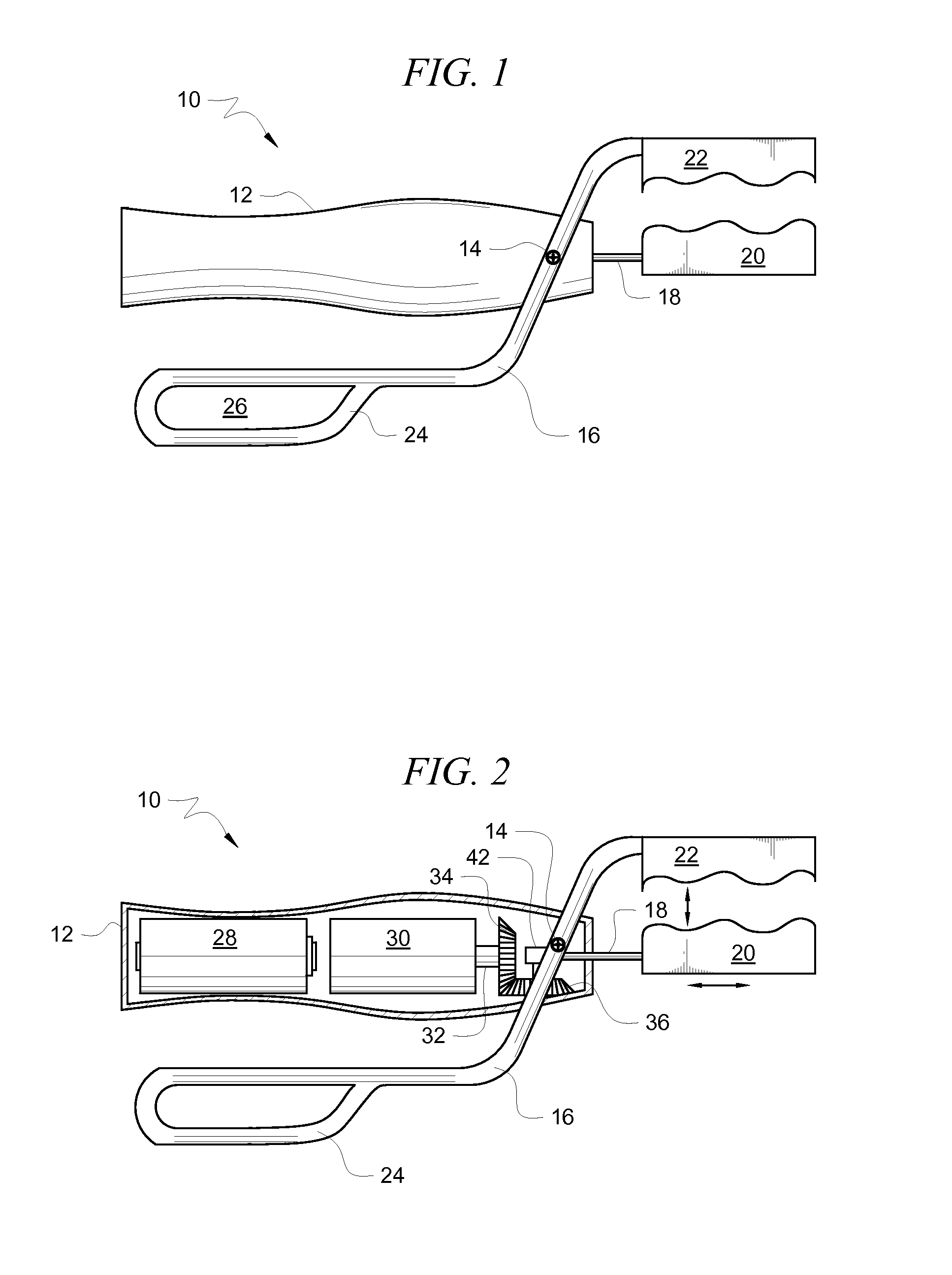
[0032] The interior of hollow handle 12 is d...

second embodiment

[0037]FIGS. 4-6 depict a second embodiment, denoted 50 as a whole. Tool 50 includes plates 20 and 22. Plate 22 is mounted for oscillation as indicated by double-headed directional arrow 52. Motor 54 could be battery operated but it is preferably in electrical communication with a power source through power cord 56. Gear box 58 includes a well-known gear train that converts the rotary motion of the power take-off shaft of motor 54 to the reciprocating motion of plate 22. Clamp 60 has a square-U shape to accommodate link 22a and is secured to gear box 58. Link 22a interconnects a gear in gear box 60 that rotates in a vertical plane with reciprocating plate 22.

[0038] Clamp 60 also accommodates and engages mounting block 62 that performs the function of interconnecting the part of tool 50 having oscillating plate 22 with the part of tool 50 having stationary plate 20.

[0039] More particularly, the distal free end of elongate adjustment rod 64 is received in a slot formed in mounting blo...


PUM


Abstract

An apparatus and method for simultaneously applying a compressive and a reciprocating force to underlying adipose cells from a location external to a patient's skin to rupture or otherwise remove the adipose cells within a subcutaneous tissue region. The adipose cells are ruptured through the mechanical application of compression and shearing forces. The patient's body then re-absorbs and expels the ruptured cells. This eliminates the need for invasive liposuction and the trauma associated with invasive liposuction. Various mechanical devices may be employed to impart the compressive and shearing forces.

Description

CROSS-REFERENCE TO RELATED APPLICATIONS [0001] This application claims the benefit of U.S. provisional patent application No. 60 / 862,779 of the same title, filed Oct. 25, 2006 by the same inventor, which application is hereby incorporated by reference in its entirety into this nonprovisional patent application.BACKGROUND OF THE INVENTION [0002]1. Field of the Invention [0003] This invention relates to an apparatus that removes adipose tissue in a noninvasive way. More particularly, it relates to a method for the removal of adipose (fat) tissue through the application of compressive and shearing forces on a target area in a patient. [0004] 2. Description of the Prior Art [0005] Liposuction is a conventional cosmetic surgical procedure for removing fat (adipose) cells from patients to achieve a desired body shape. Liposuction usually involves an invasive surgical procedure that includes penetrating the skin, melting or shearing adipose tissue, and mechanically removing adipose tissue ...

Claims


Application Information

Patent Timeline
Patent Type & Authority Applications(United States)
IPC IPC(8): A61H99/00
CPCA61H7/007A61H23/0254A61H2201/1669A61H2201/1215A61H2201/0153
Inventor ADAMSON, CHRISTOPHER D.
Owner ADAMSON CHRISTOPHER D
Why Eureka
Try Eureka