Adipose tissue separation device and methods

a tissue separation and adipose technology, applied in the field of tissue separation devices, can solve the problems of reducing the likelihood of tissue rejection, affecting the efficiency of liposuction procedures, and affecting the efficiency of liposuction,

Active Publication Date: 2016-06-07
VENTURI MARK LOUIS
View PDF11 Cites 21 Cited by
  • Summary
  • Abstract
  • Description
  • Claims
  • Application Information

AI Technical Summary

Benefits of technology

[0006]The present teachings provide a tissue separating device including a canister device including a canister body having a sidewall defining a volume. A tissue retrieval port can be arranged on the canister device and can be capable of being arranged in fluid communication with a harvesting device for directing a fatty liposuction aspirate into the volume of the canister device. An adjustable height filtration mesh assembly can be arranged within the canister body and can include a filtering mesh separating the volume into an upper vacuum chamber and a lower vacuum chamber. A tissue harvesting port can be arranged in the sidewall of the canister body and can be capable of being arranged in communication with a collection device to allow the tissue harvesting port to atraumatically receive a filtered pure fat collected on the filtering mesh within the upper vacuum chamber. The filtration mesh assembly can be movably arranged within the canister body such that the filtering mesh is adjustable with respect to the tissue harvesting port.
[0007]The present teachings also provide a tissue separating device including a canister device including a canister body and a lid. The canister device can define an interior volume. An adjustable filtration mesh assembly can include a movable rod and a filtering mesh arranged in the canister body and separating the interior volume into an upper vacuum chamber and a lower vacuum chamber. A height of the filtering mesh within the canister body is capable of being adjusted by adjusting the movable rod on an exterior of the canister body. A tissue retrieval port can be arranged on the canister device and can be capable of being in fluid communication with a harvesting device for directing a fatty liposuction aspirate onto the filtering mesh of the filtration mesh assembly within the upper vacuum chamber. A tissue harvesting port can be arranged in the sidewall of the canister body and can be capable of being arranged in communication with a collection device. The filtering mesh can be adjustable with respect to the tissue harvesting port for facilitating the atraumatic removal of filtered pure fat collected on the filtering mesh from the upper vacuum chamber of the canister body.

Problems solved by technology

However, the adipose cells are relatively delicate and the number of steps and length of time required to separate and process the harvested tissue prior to re-introduction into the patient contributes directly to the success of the operation and decreases the likelihood the tissue will be rejected.
However, the nature of liposuction procedures preclude easy tissue isolation after initial harvest, especially on a large scale, because the volume and / or viscosity of the extracted liposuction effluent also contains unwanted components such as oil, blood and anesthetic solution.
Currently, there are no standard techniques, methods, or devices that exist for the simple, large scale isolation and refinement of liposuction-harvested adipose tissue.
Although a number of specialized cannulas, needles and methods for tissue harvest and preparation exist, these techniques are tedious and inefficient.
Known centrifuge-free processes require a large number of steps which result in a cumbersome harvesting and re-injection process that leaves room for much improvement.

Method used


Image

  • Adipose tissue separation device and methods
  • Adipose tissue separation device and methods
  • Adipose tissue separation device and methods

Examples


Embodiment Construction

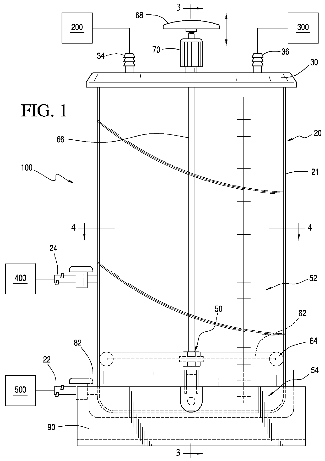
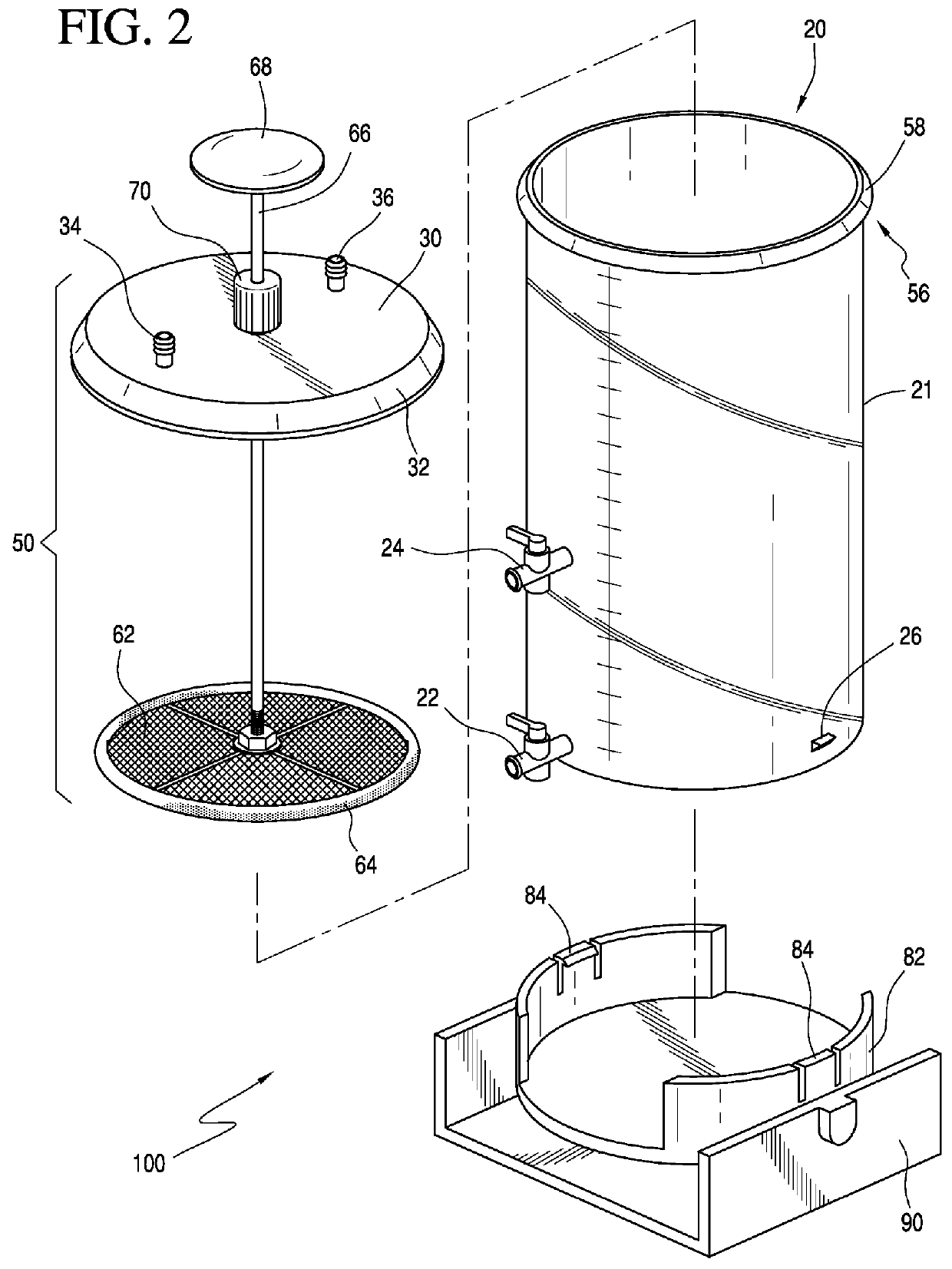
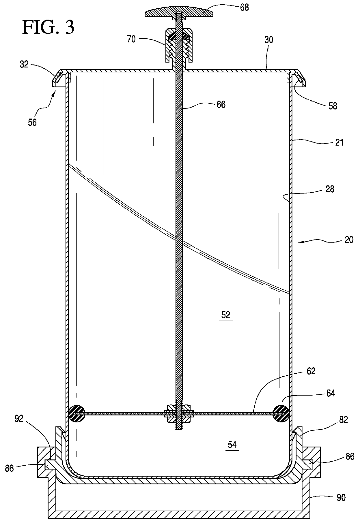
[0015]Referring to at least FIG. 1, a tissue separating device 100 in accordance with a preferred embodiment of the present teachings is shown. The tissue separating device 100 can include a canister device 20 including a canister body 21 and a lid 30. The canister device 20 can include a vacuum connector 34 and a tissue retrieval port 36 which can be arranged in the lid 30. The vacuum connector 34 can be operatively coupled to a vacuum source 200 via tubing. The tissue retrieval port 36 can be operatively coupled to a harvesting device 300 via a liposuction cannula. A sidewall of the canister body 21 can include a fluid evacuation port 22 and a tissue harvesting port 24. The tissue separating device 100 also includes an adjustable height filtration mesh assembly 50 that is operable to divide the interior of the canister device 20 into an upper vacuum chamber 52 and a lower vacuum chamber 54.

[0016]In use, a quantity of fatty liposuction aspirate can be directed into the canister dev...


PUM


Abstract

A tissue separating device and a method of separating pure fat from a fatty liposuction aspirate are provided. The tissue separating device includes a canister device including canister body having a sidewall defining a volume. A tissue retrieval port can be arranged on the canister device and is capable of being arranged in fluid communication with a harvesting device for directing a fatty liposuction aspirate into the volume of the canister device. An adjustable height filtration mesh assembly can be arranged within the canister body and can include a filtering mesh separating the volume into an upper vacuum chamber and a lower vacuum chamber. A tissue harvesting port can be arranged in the sidewall of the canister body and can be capable of being arranged in communication with a collection device to allow the tissue harvesting port to atraumatically receive a filtered pure fat collected on the filtering mesh within the upper vacuum chamber. The filtration mesh assembly can be movably arranged within the canister body such that the filtering mesh is adjustable with respect to the tissue harvesting port.

Description

FIELD OF THE INVENTION[0001]The present teachings relate to a tissue separating device for body fluids and tissue specimens. In particular, the present teachings relate to a separation device for use with a suction source to withdraw and separate body fluids and tissue specimens from a patient in an atraumatic manner.BACKGROUND OF THE INVENTION[0002]Autologous adipose tissue (or fatty tissue) transplantation is performed by many surgeons for various cosmetic and reconstructive procedures. Autologous fat transplantation involves retrieving adipose tissue using liposuction techniques from an area of abundance and then re-injecting the harvested adipose tissue into a different site of the same individual for cosmetic / reconstructive augmentation or enhancement purposes. Generally, prior to the re-introduction of the tissue into the patient, the adipose tissue must be processed or cleaned to maximize the chances of implant survival. Such processing is preferably accomplished while minimi...

Claims


Application Information

Patent Timeline
Patent Type & Authority Patents(United States)
IPC IPC(8): A61M1/00A61M5/178A61M5/00A61M5/315A61M27/00
CPCA61M1/0068A61M2202/0014A61M2202/0021A61M2202/09A61M2205/7545C12M45/02C12M47/02A61M2202/08A61M1/63A61M1/88A61M1/892A61M1/81
Inventor VENTURI, MARK LOUIS
Owner VENTURI MARK LOUIS
Why Eureka
Try Eureka