
Spinal-column buttress plate assembly and method for attachment

a technology of spine and buttress plate, applied in the field of spine-column buttress plate assembly and method of attachment, can solve problems such as attachment problems, and achieve the effects of less attachment strength, less mechanical stability, and maximum attachment strength and mechanical stability

Inactive Publication Date: 2005-06-23
UWAYDAH MUNIR
View PDF6 Cites 16 Cited by
  • Summary
  • Abstract
  • Description
  • Claims
  • Application Information

AI Technical Summary

Benefits of technology

[0011] Several benefits and advantages are derived from the invention. The apparatus and method of the invention allows a physician to choose an optimum location for the first bone screw on the first vertebral body (e.g., on the first cervical vertebral body) and to choose an optimum location for the second bone screw on the second vertebral body (e.g., on the second cervical vertebral body) for maximum attachment strength and mechanical stability. This is accomplished by first installing the bone screws on the vertebral bodies and then securing the buttress plate to the installed bone screws. In comparison, the prior art forces the physician to use pre-drilled holes in the buttress plate which often provide less than optimum attachment locations (providing less attachment strength and less mechanical stability) for the bone screws to be installed in the vertebral bodies.

Problems solved by technology

Attachment problems arise when the pre-drilled holes of the spinal-column buttress plate are only alignable over a non-optimum area of the first and / or second vertebral body.

Method used


Image

  • Spinal-column buttress plate assembly and method for attachment
  • Spinal-column buttress plate assembly and method for attachment
  • Spinal-column buttress plate assembly and method for attachment

Examples


Embodiment Construction

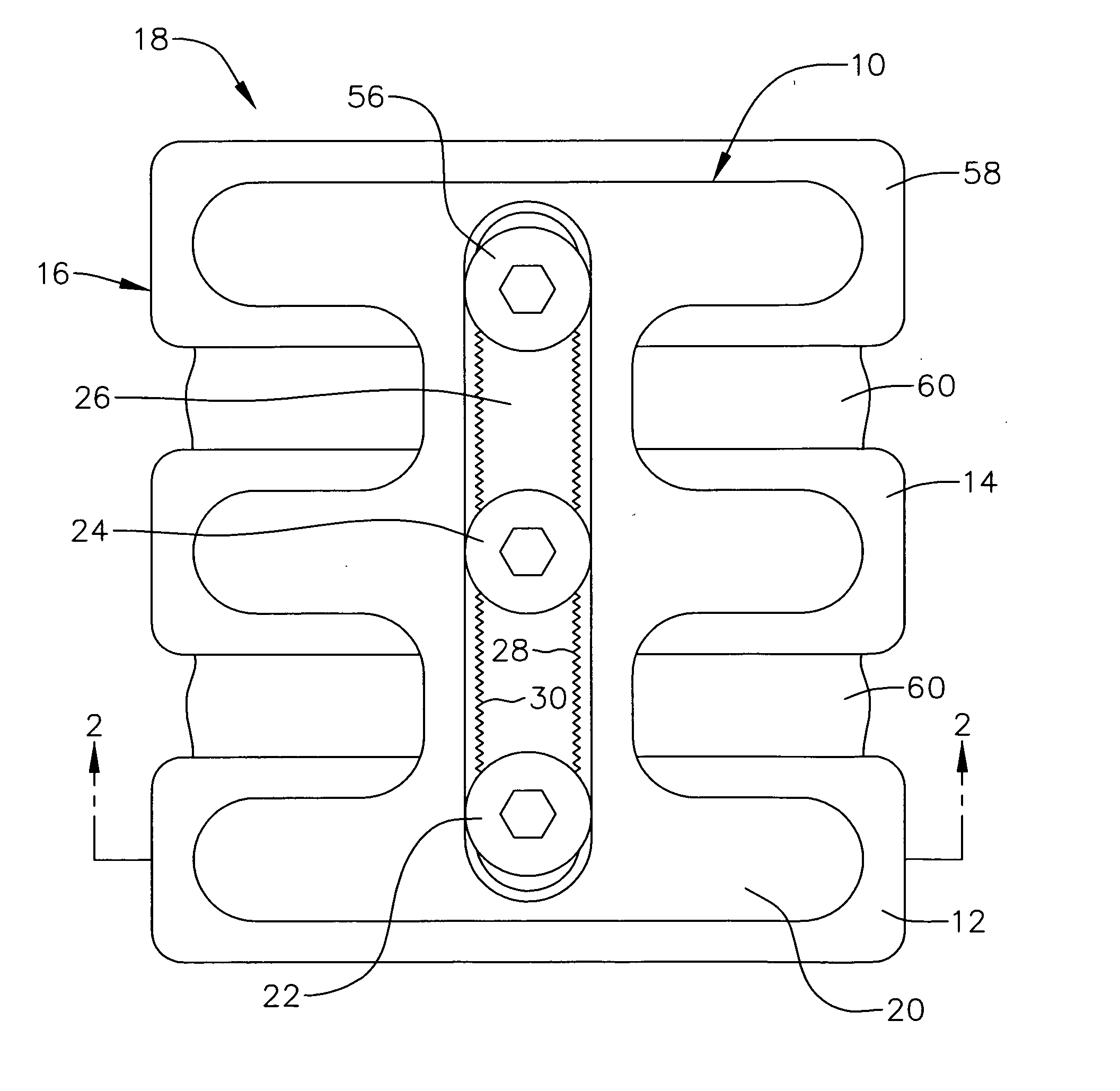
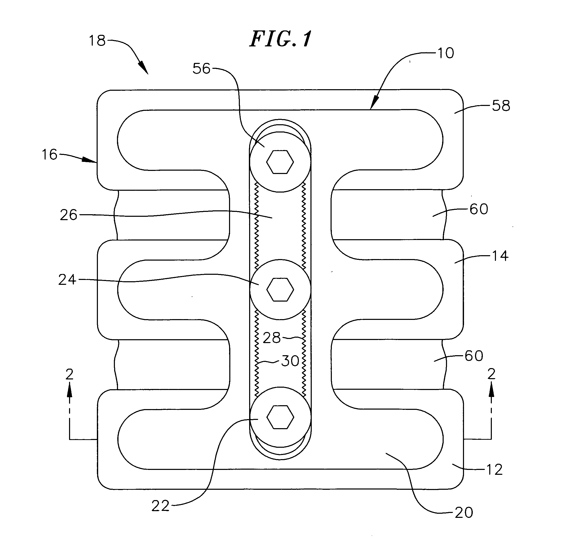
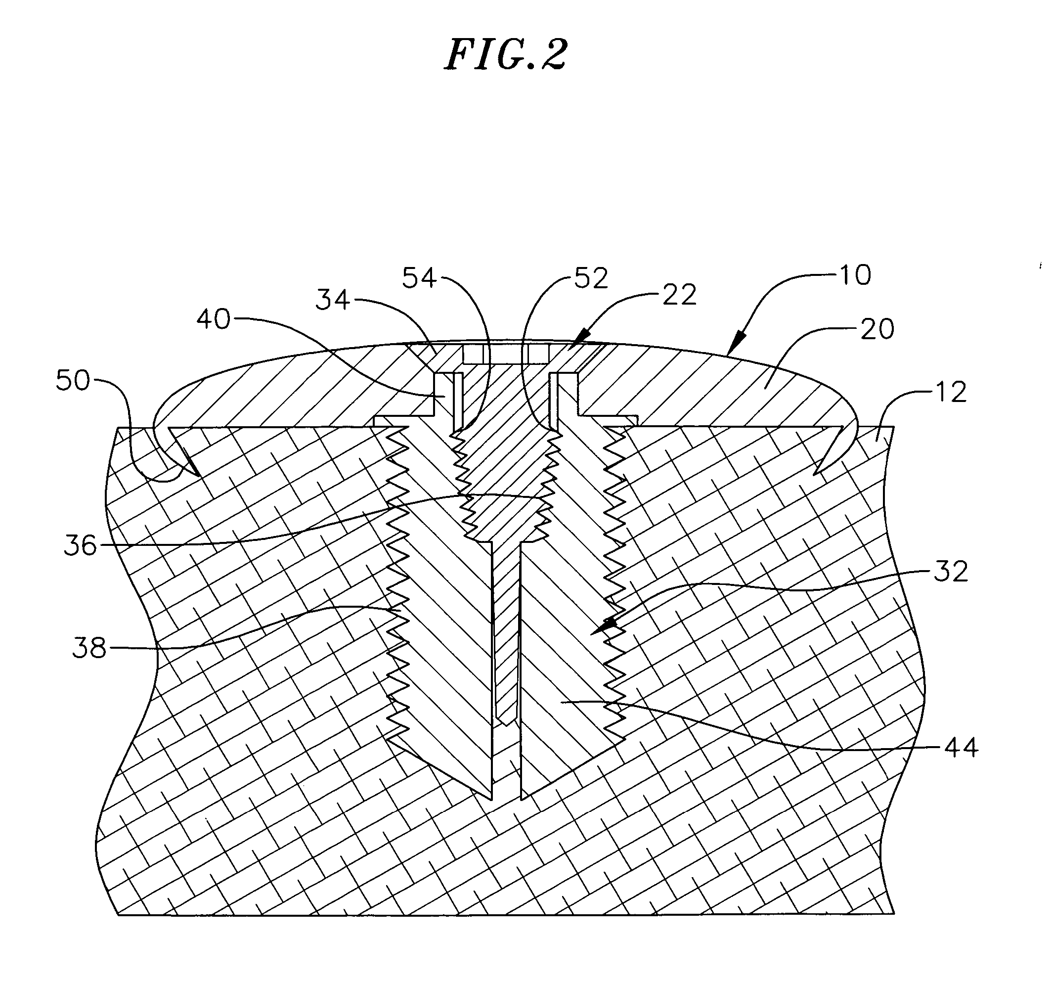
[0021] A preferred embodiment of the invention, shown in FIGS. 1-8, is for a spinal-column buttress plate assembly 10 for attaching together first and second vertebral bodies 12 and 14 of a spinal column 16 of a medical patient 18 (only a portion of the spinal column of whom is shown in FIG. 1). Preferably, the spinal column 16 is a cervical column, the first and second vertebral bodies 12 and 14 are first and second cervical vertebral bodies, the spinal-column buttress plate assembly 10 is a cervical-column buttress plate assembly, and the spinal-column buttress plate assembly 10 is for fusing together the first and second cervical vertebral bodies of the cervical column of the medical patient. Preferably, the cervical-column buttress plate assembly is an anterior cervical-column buttress plate assembly. In other medical procedures, the first and second vertebral bodies 12 and 14 are vertebral bodies of an upper back portion and / or a lower back portion of the spinal column. Prefera...


PUM


Abstract

A spinal-column (e.g., cervical-column) buttress plate assembly and method for attaching together first and second vertebral bodies of a spinal column (e.g., cervical column) of a medical patient. Bone screws are inserted into the vertebral bodies at optimum locations on the vertebral bodies. A buttress plate having an elongated slot is placed on the vertebral bodies so that the heads of the bone screws are positioned in the elongated slot. Inner screws are threaded into the bone screws to expand their heads against the opposing edges of the elongated slot thereby attaching the buttress plate to the vertebral bodies.

Description

BACKGROUND OF THE INVENTION [0001] The present invention relates generally to medical apparatus and procedures, and more particularly to apparatus and a method which attaches a spinal-column buttress plate to two vertebral bodies of a spinal column of a medical patient. [0002] Conventional medical procedures include attaching together (sometimes called fusing) first and second vertebral bodies of a spinal column (such as adjacent first and second cervical vertebral bodies of the cervical column portion of the spinal column) of a medical patient. A spinal-vertebral buttress plate (such as a cervical-vertebral buttress plate) of appropriate length is obtained. The buttress plate is positioned on the anterior side of the first and second vertebral bodies. The buttress plate comes with pre-drilled holes. Using first and second holes, of the positioned buttress plate, which are aligned over the first vertebral body, first and second starter holes are marked and drilled on the anterior co...

Claims


Application Information

Patent Timeline
IPC IPC(8): A61B17/70A61B17/80
CPCA61B17/8038A61B17/7059
Inventor UWAYDAH, MUNIR
Owner UWAYDAH MUNIR
Learn More