Flexible distributed manufacturing method and system therefor

a manufacturing method and distributed manufacturing technology, applied in the field of sheet metal manufacturing, can solve the problems of limiting the capability and capacity of the manufacturer to produce parts, not allowing any flexibility during the manufacturing process, and unable to produce the correct flat drawing in a conventional manufacturing environmen

Active Publication Date: 2005-06-23
FINN POWER INT
View PDF4 Cites 11 Cited by
  • Summary
  • Abstract
  • Description
  • Claims
  • Application Information

AI Technical Summary

Benefits of technology

[0013] In those instances where multiple parts are to be produced by different operations, and therefore different machines of the system, the various operations are separated out and the relevant data from the various databases are retrieved for each of the operations so that the appropriate machines may be selected for the different operations that are required for fabricating the different input parts

Problems solved by technology

Currently, there are several problems that are created when a flat drawing is produced.
And if the dimensions of a component are critical, or if the component has multiple bends at different directions, the generation of a correct flat drawing in a conventional manufacturing environment becomes quite difficult, as an accurate flat drawing requires information based on the tooling, the material, and the machine, etc. in-combination.
Once a flat drawing is generated for a manufacturing process, the manufacturing process is “locked” to that flat drawing and therefore does not allow any flexibility during t

Method used


Image

  • Flexible distributed manufacturing method and system therefor
  • Flexible distributed manufacturing method and system therefor
  • Flexible distributed manufacturing method and system therefor

Examples


Embodiment Construction

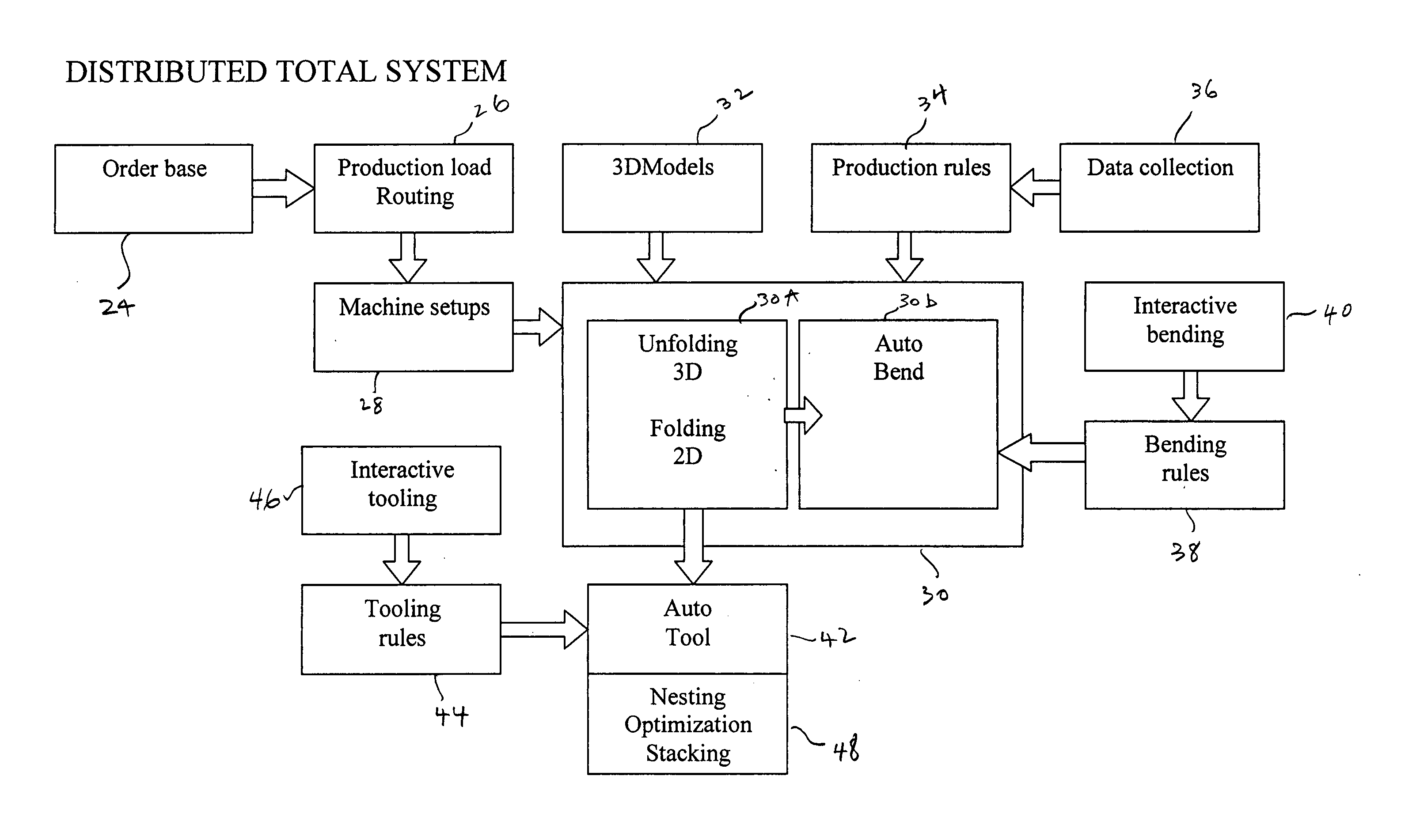
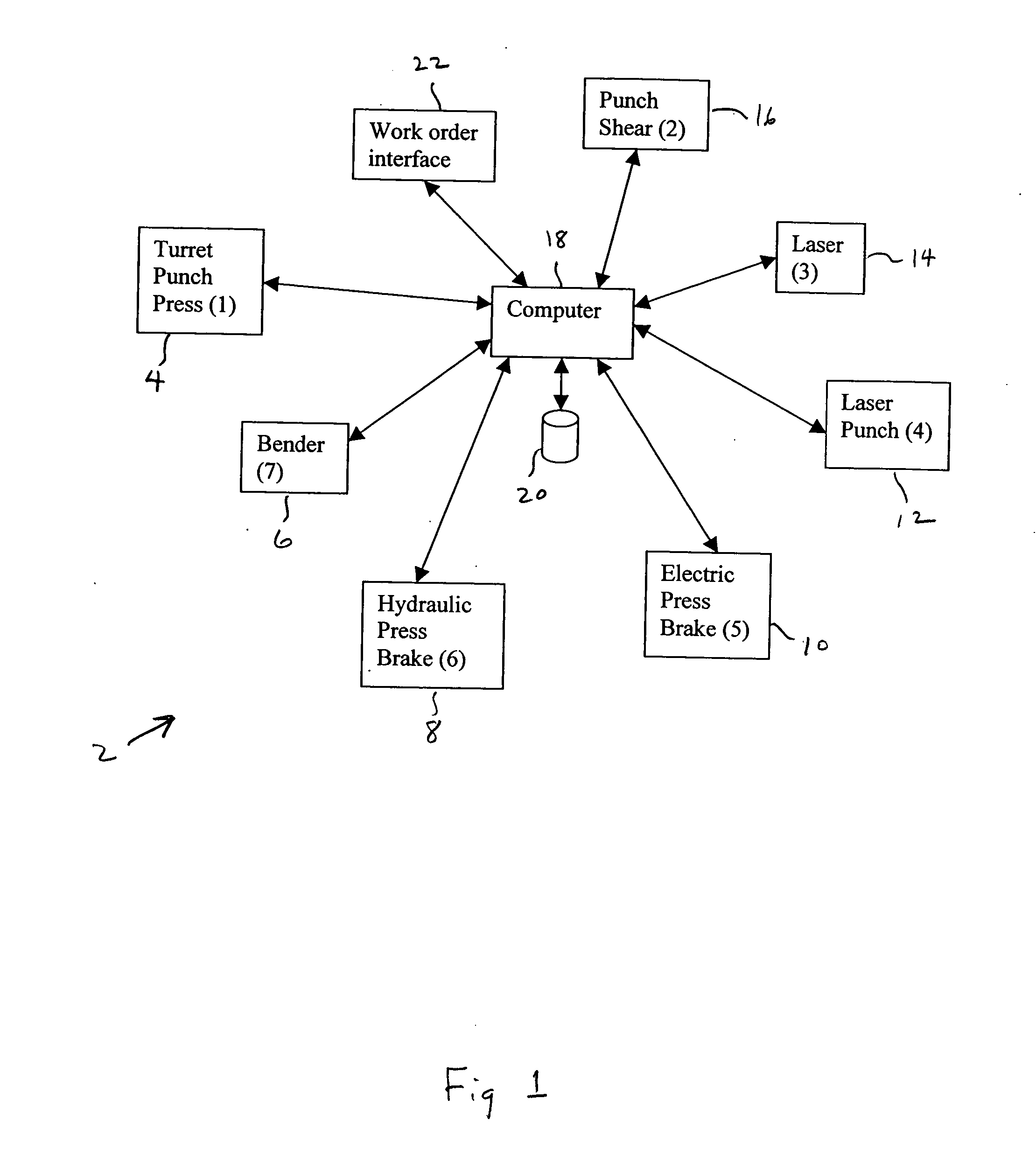
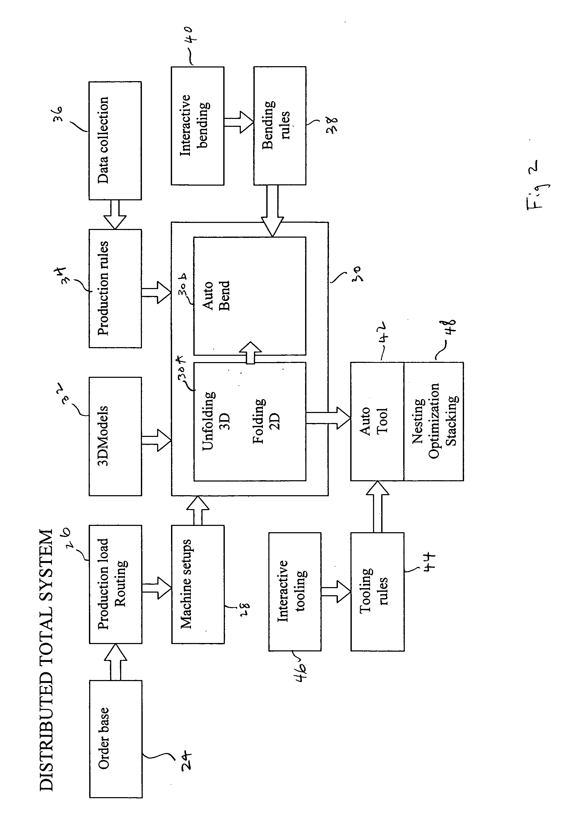
[0023] A distributed flexible manufacturing system is illustrated in FIG. 1. As shown, the exemplar manufacturing system 2 includes a turret punch press 4, a bender machine 6, a hydraulic press brake 8, an electric press brake 10, a laser punch 12, a laser cutter 14 and a punch shear 16. Each of those machines is connected to a central processing computer 18. It should be noted that computer 18 may in fact be representative of the individual CNC controllers or any one of the CNC controllers resident in each of the sheet fabrication machines of the FIG. 1 embodiment.

[0024] Connected to computer 18 is a memory 20. Memory 20, instead of being a central memory, may also be representative of the individual memory resident in each of the sheet fabrication machines that functions with the resident CNC controller in those machines. A work order interface 22 is also connected to computer 18 for receiving input orders for the fabrication of worksheets. Such interface may include conventional...


PUM


Abstract

In a manufacturing system that has a plurality of sheet fabrication machines, to enhance the efficiency of the system, there are provided a plurality of databases each for storing particular data relating to the machines, the types of materials to be used, the tooling of the machines, etc. of the system. When a multi-dimensional model of a component part to be produced by the system is input to the system, selective data is retrieved from the various databases so that at least one machine of the plurality of machines of the system is selected to produce the part from a worksheet of a chosen material. Concurrently, or shortly thereafter, a NC part program for programming the selected machine to execute the necessary operations in accordance with a flat drawing generated from the multi-dimensional model to fabricate the component part is generated based on selective data retrieved from the databases. With the NC part program, the selected machine performs the operations necessary for producing the component part from the sheet stock material chosen for the component part. If there are multiple component parts to be produced in the same production run, the system would sort the different parts and arrange for the ordered fabrication of the different parts by respective selected machines equipped with corresponding appropriate NC programs to eliminate any potential bottleneck or conflicts that may arise due to the fabrication of multiple parts by multiple machines during the same production run.

Description

FIELD OF THE INVENTION [0001] The present invention relates to sheet metal manufacturing and particularly to a flexible distributed manufacturing method, and system therefor, that selects from among a plurality of machines of a distributed sheet metal manufacturing system one that is adaptable to fabricate a part at a particular time from an input order, with the ordered part being represented by a multidimensional model or drawing. BACKGROUND OF THE INVENTION [0002] In the current sheet metal manufacturing environment, flat metal parts are produced by individual sheet fabrication machines such as for example punch presses, laser cutters, and / or combinations thereof. For bending, the flat metal pieces are bent by machines such as benders, press brakes and automatic panel bending machines, etc. With the advance of the CNC (Computer Numerical Controlled) technology, all of these individual machines can be programmed to perform the tasks with which the machines are designed for. For ex...

Claims


Application Information

Patent Timeline
IPC IPC(8): G05B19/418G06F19/00
CPCG05B19/41865G05B2219/31325Y10S707/99945G05B2219/32283G05B2219/45234G05B2219/32062Y02P80/40Y02P90/02
Inventor LINDSTROM, MIKKOHAAG, MIKAEL
Owner FINN POWER INT
Why Eureka
Try Eureka