Portable computer support structure

a support structure and portable computer technology, applied in the direction of electrical apparatus casings/cabinets/drawers, furniture parts, instruments, etc., can solve the problems of inconvenience in the use of portable computers, and cannot meet different body heights, and achieve the effect of eliminating the problem of reflection of ligh

Inactive Publication Date: 2005-06-30
TATUNG COMPANY
View PDF10 Cites 61 Cited by
  • Summary
  • Abstract
  • Description
  • Claims
  • Application Information

AI Technical Summary

Benefits of technology

[0007] The present invention has been accomplished under the circumstances in view. It is the main object of the present invention to provide a portable computer support structure, which can conveniently be controlled to adjust the angle of the tablet PC supported thereon subject to the user's body height, giving convenience of use.
[0010] When in use, the user can freely adjust the angle of inclination of the portable computer to the best view angle subject to the user's body height by using the step-less shaft of the step-less pivoting device, eliminating the problem of reflection of light of the display screen. And the portable computer can be held in the desired angular position for convenience of use.

Problems solved by technology

However, a conventional portable computer support structure is simply adapted to support the portable computer in the standing position, not adjustable to change the standing angle of the portable computer.
Because this design of portable computer support structure is not adjustable, it does not fit different users of different body heights.
Further, this limitation causes a number of problems as excessively high or low view angle, reflection of the light of the display screen, etc., resulting in inconvenience use of the portable computer.

Method used


Image

  • Portable computer support structure
  • Portable computer support structure
  • Portable computer support structure

Examples


Embodiment Construction

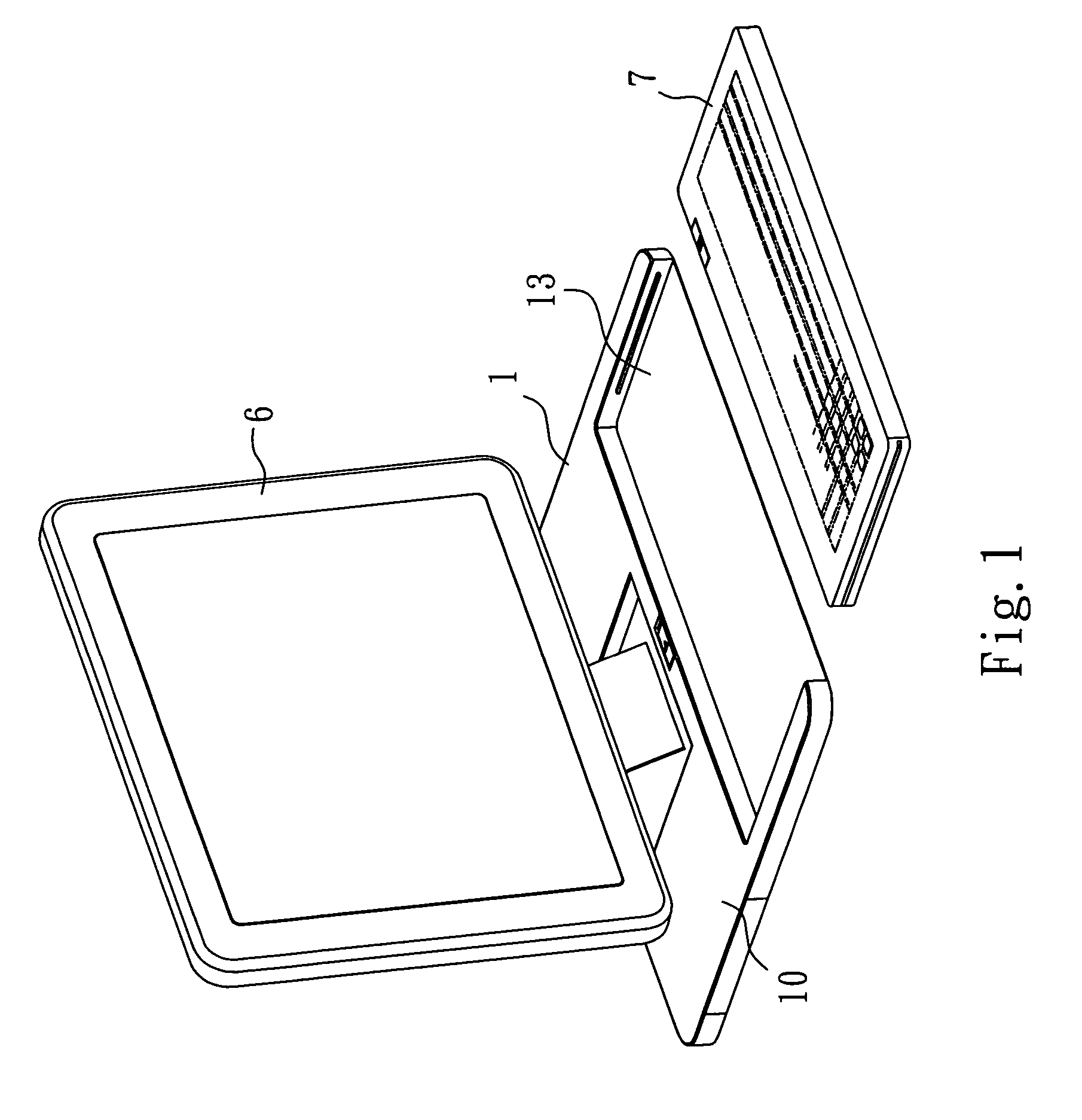
[0016] Referring to FIG. 1, a portable computer support structure in accordance with the present invention is shown comprised of a base member 1 and a portable computer 6 supportable on the base member 1. The portable computer 6 according to the present preferred embodiment is a tablet PC. The base member 1 has a receiving open chamber 13, which accommodates an input device, for example, a keyboard 7.

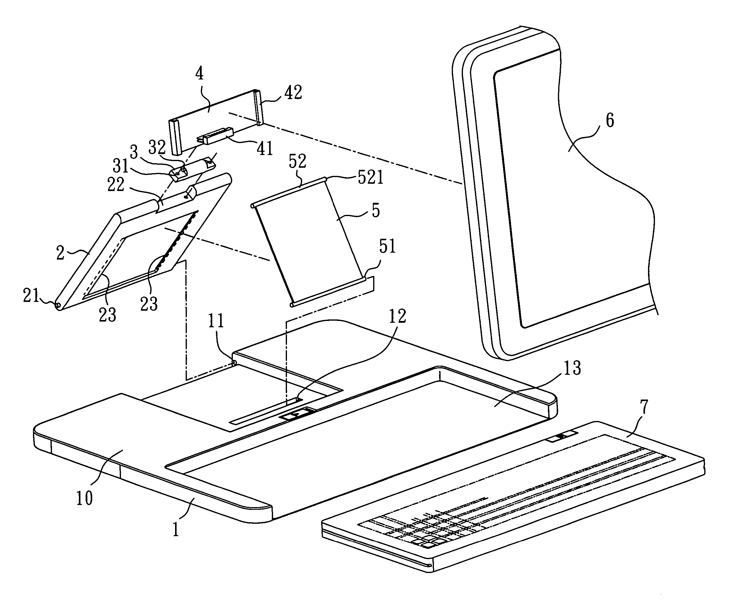
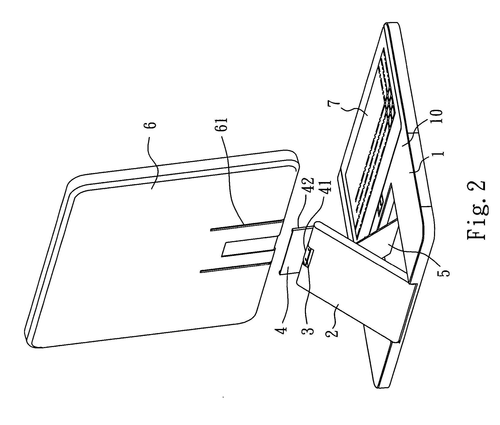
[0017] Referring to FIGS. 2 and 3 and FIG. 1 again, the portable computer 6 comprises a pair of sliding grooves disposed at the back surface, forming a supporting portion 61. The portable computer support structure further comprises a support arm 2, a back-stick plate 5, a step-less pivoting device 3, and a support block 4.

[0018] The base member 1 has provided at the top surface 10 a first pivoting structure 11 near the rear side of the base member 1 and a second pivoting structure 12 in front of the first pivoting structure 11. The support arm 2 has a bottom pivoting portion 21 at th...


PUM


Abstract

A portable computer support structure is constructed to include a base member, a support arm fastened pivotally with the base member, a back-stick plate pivoted to the base member and adapted to adjustably support the support arm above the base member in a standing position, a step-less pivoting device affixed to the top side of the support arm and holding a step-less shaft, and a support block fastened to the step-less shaft and adapted to support a portable computer for enabling the portable computer to be rotated with the step-less shaft relative to the support arm to adjust the view angle and to prevent the problem of reflection of light of the display screen.

Description

BACKGROUND OF THE INVENTION [0001] 1. Field of the Invention [0002] The present invention relates to a portable computer support structure and more particularly, to such a portable computer support structure, which is practical in use to support a portable computer, enabling the portable computer to be adjusted to the desired a standing operative angle. [0003] 2. Description of Related Art [0004] In order to support a portable computer, for example, a tablet PC in a standing position for operation, a support structure may be used to support the portable computer in position. [0005] However, a conventional portable computer support structure is simply adapted to support the portable computer in the standing position, not adjustable to change the standing angle of the portable computer. Because this design of portable computer support structure is not adjustable, it does not fit different users of different body heights. Further, this limitation causes a number of problems as excessiv...

Claims


Application Information

Patent Timeline
Patent Type & Authority Applications(United States)
IPC IPC(8): F16M11/10G06F1/16
CPCF16M11/10F16M2200/024Y10S248/923G06F1/1626G06F1/1632F16M2200/08
Inventor CHEN, CHING-JOUHUANG, CHAO-MINGCHANG, KAO-WEN
Owner TATUNG COMPANY
Why Eureka
Try Eureka