Circuit breaker structure

a circuit breaker and structure technology, applied in the direction of circuit breaker switches, circuit breaker switches for excess current, protection switch operating/releasing mechanisms, etc., to achieve the effect of improving the structure of the circuit breaker

Inactive Publication Date: 2005-06-30
KUO WAN KUO
View PDF30 Cites 10 Cited by
  • Summary
  • Abstract
  • Description
  • Claims
  • Application Information

AI Technical Summary

Benefits of technology

[0012] The primary purpose of the present invention is to provide an improved structure of a circuit breaker, which mainly comprises of a housing, a rocker-switch, a push-shaft, a pull-shaft, a bimetallic strip, and other parts. The rocker-switch is installed on the top of the housing. Inside the housing and underneath the rocker-switch, there are three electrical terminals. Both the pull-shaft and the push-shaft are connected to the tilted plate underneath the rocker-switch. The pull-shaft and the push-shaft are connected to a common terminal through a slotted opening inside the housing. One end of the bimetallic strip is installed at the raised portion of the terminal, and the bimetallic strip is also connec

Problems solved by technology

Secondly, under the overloading condition, the spring installed on the housing expands and causes push-shaft to press the silver point

Method used


Image

  • Circuit breaker structure
  • Circuit breaker structure
  • Circuit breaker structure

Examples


Embodiment Construction

[0024] The following descriptions are of exemplary embodiments only, and are not intended to limit the scope, applicability or configuration of the invention in any way. Rather, the following description provides a convenient illustration for implementing exemplary embodiments of the invention. Various changes to the described embodiments may be made in the function and arrangement of the elements described without departing from the scope of the invention as set forth in the appended claims.

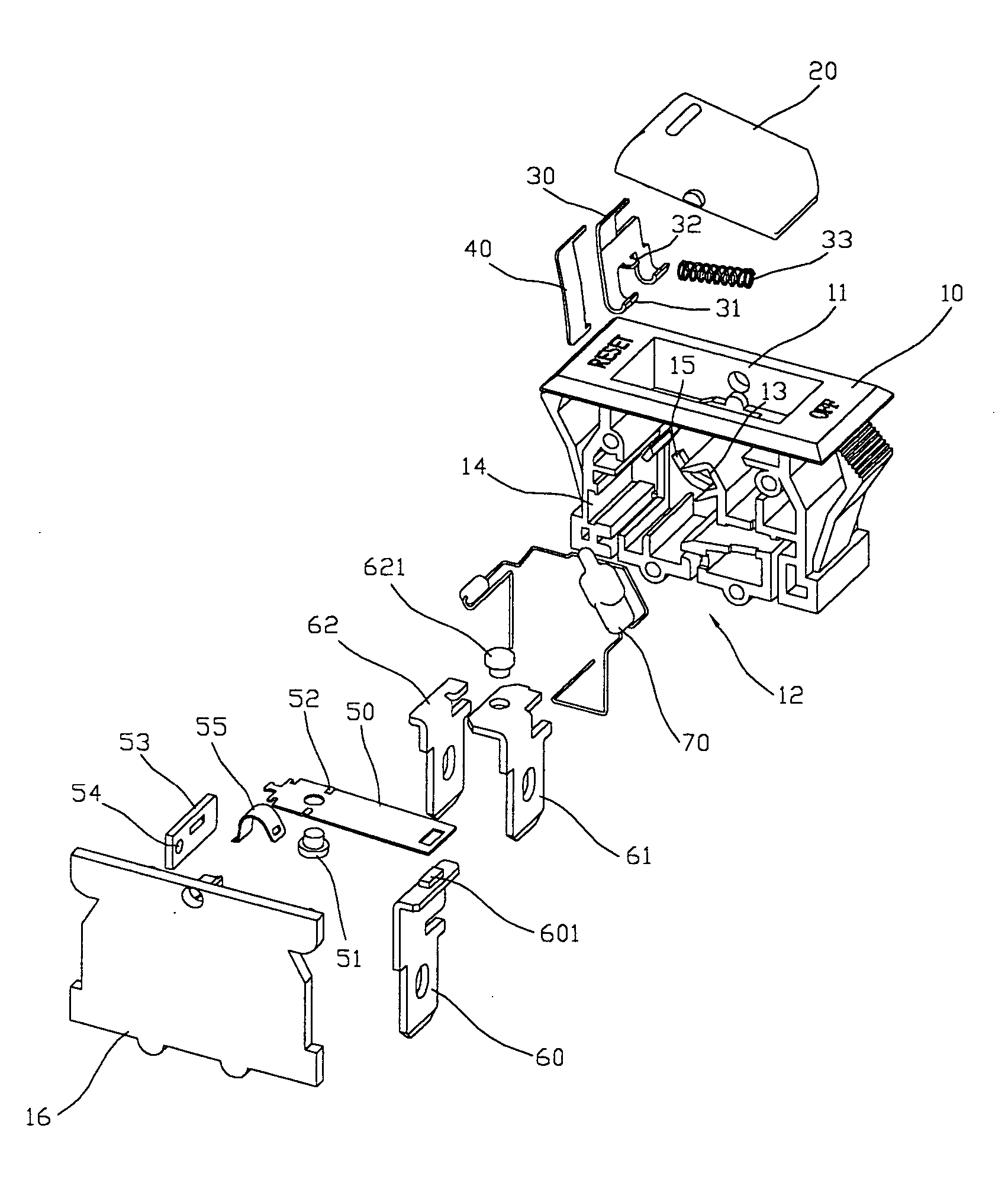
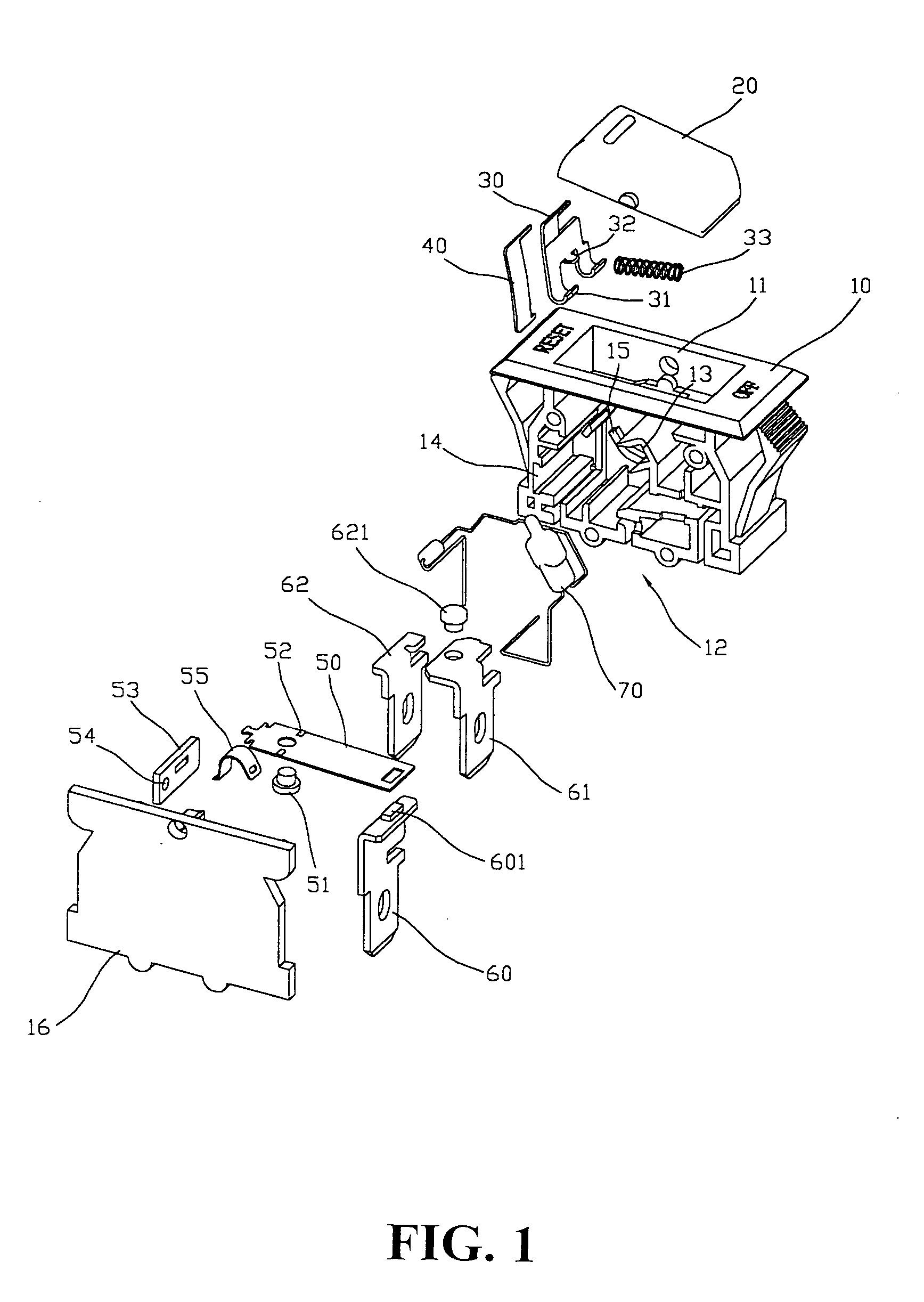
[0025] In the following, detailed description along with the accompanied drawings explains fully the preferred embodiments of the present invention. As shown in FIG. 1, the present invention is an embodiment of improved structure of a circuit breaker comprising of a housing 10, a rocker-switch 20, a push-shaft 30, a pull-shaft 40, a bimetallic strip 50, three terminals 60, 61, and 62 with corresponding pivoted connections, an indicator 70, a side cover on the housing 16 to constitute a one-piec...


PUM


Abstract

An improved structure of a circuit breaker is provided which comprises a housing, a rocker-switch, a push-shaft, a pull-shaft, a bimetallic strip, and other parts. There are three terminals under the rocker-switch inside the housing. A bimetallic strip embedded in a groove under the pull-shaft makes contact with that pull-shaft through a silver point at one end. The bimetallic strip also makes contact with the push-shaft at the other end using another silver point. Both the pull-shaft and the push-shaft are connected with a curved spring installed inside the V-shaped slot on an adjustment strip. The bimetallic strip, curved spring, and both the pull-shaft and the push-shaft constitute the main control mechanism that provides the circuit breaking action under overloading condition.

Description

BACKGROUND OF THE INVENTION [0001] (a) Technical Field of the Invention [0002] The present invention generally relates to circuit breaking devices, and more particularly to an improved circuit breaker structure that returns the circuit breaker back to the OFF state automatically. [0003] (b) Description of the Prior Art [0004] The ordinary circuit breakers utilize the ON and OFF action mechanism to prevent overheating, fire, and other hazardous accidents as a result of current overloading in electrical circuitries. The circuit breaker also has the characteristic of being able to return back to closed-circuit state after overloading condition is eliminated. However, safer, simplified operating mechanism and lower cost are still pursued by circuit breaker manufacturers. [0005] Reviewing two previously awarded patent rights can provide an understanding of the mechanisms and shortcomings of prior arts of making circuit breakers. [0006] The first one reviewed is Patent Number 208384, A Ci...

Claims


Application Information

Patent Timeline
IPC IPC(8): H01H73/26
CPCH01H73/26
Inventor KUO, WAN-KUO
Owner KUO WAN KUO
Why Eureka
Try Eureka