Variable candela strobe with constant trigger voltage

a candela strobe and trigger voltage technology, applied in the field of strobe devices, can solve the problems of excessive trigger voltage at high candela outputs, insufficient trigger voltage to produce reliable ignition of flash tubes, and limit the range of candela that can be reliably achieved

Inactive Publication Date: 2005-06-30
HONEYWELL INT INC
View PDF18 Cites 1 Cited by
  • Summary
  • Abstract
  • Description
  • Claims
  • Application Information

AI Technical Summary

Problems solved by technology

However, there are limitations on the range of candela (intensity) that can be reliably achieved.
One problem is that to flash the tube requires that the voltage across it be greater than a predetermined threshold amount (e.g. 180 volts) for reliable operation.
Thus, the trigger voltage may be excessive at high candela outputs.
Additionally, at low candela settings, the trigger voltage may not be high enough to produce reliable ignition of the flash tube LP1.
At high candela settings, the voltage can become so high that the transformer may start to arc and to fail.
While known devices provide a selectable candela output, the use of a voltage doubler does have some disadvantages.
In addition, in compact units with the circuitry implemented on a printed circuit board, arcing is a potential problem.

Method used


Image

  • Variable candela strobe with constant trigger voltage
  • Variable candela strobe with constant trigger voltage
  • Variable candela strobe with constant trigger voltage

Examples


Embodiment Construction

[0018] While embodiments of this invention can take many different forms, specific embodiments thereof are shown in the drawings and will be described herein in detail with the understanding that the present disclosure is to be considered as an exemplification of the principles of the invention and is not intended to limit the invention to the specific embodiment illustrated.

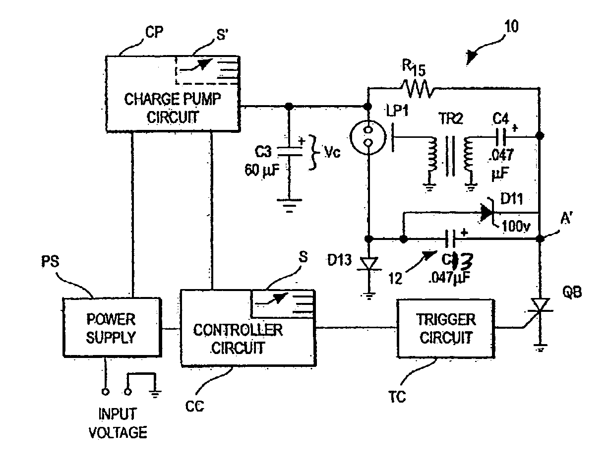
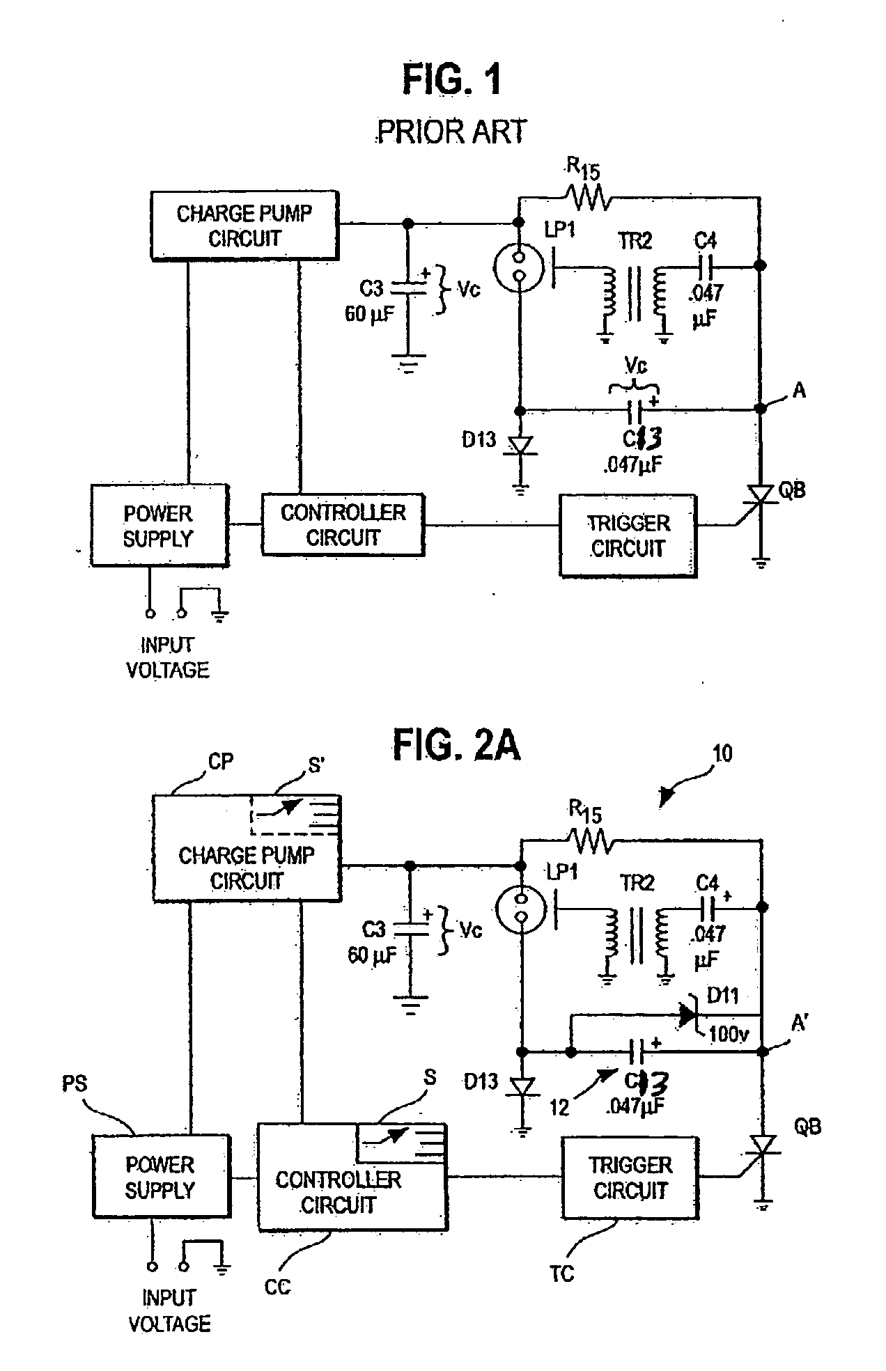
[0019] The disadvantages of the prior art above can be overcome with a power supply in accordance with the invention. A more controlled voltage is achieved across the flash tube using a voltage booster circuit that is not a “doubler” but rather an “adder” type circuit. The present circuit operates significantly differently than the prior art circuits. The parent application hereto Ser. No. 10 / 429,900 filed May 5, 2003 and assigned to the assignee hereof is hereby incorporated by reference.

[0020] It would be advantageous to achieve a broad candela range, for example 15-185 candela, by adjusting the charge pump ...


PUM


Abstract

A variable candela strobe unit couples a substantially constant trigger voltage to a trigger electrode of a gas discharge tube irrespective of the voltage provided across the tube which is specified by a selected candela output value. The trigger voltage is great enough at low candela output settings to provide reliable triggering. It is not high enough even at the highest output settings to cause arcing of the associated step-up transformer.

Description

CROSS REFERENCE TO RELATED APPLICATION [0001] This is a continuation-in-part application of U.S. patent application Ser. No. 10 / 429,900 filed May 5, 2003, entitled “Variable Candela Strobe”.FIELD OF THE INVENTION [0002] The invention pertains to strobe devices of a type used in alarm systems. More particularly, the invention pertains to strobe devices with selectable candela outputs. BACKGROUND OF THE INVENTION [0003] Strobe devices require the application of a relatively high voltage across a flash tube in order to produce a gaseous discharge in the tube. In known devices, this high voltage is achieved by using a charge pump to transfer energy to an internal capacitor from an external energy source. The external source typically can be nominally 12 volts or 24 volts. [0004] The capacitor is coupled in parallel with the flash tube and provides the energy for the flash. The amount of light from the flash tube is directly proportional to the energy stored in the capacitor that is disc...

Claims


Application Information

Patent Timeline
Patent Type & Authority Applications(United States)
IPC IPC(8): G08B5/38
CPCG08B5/38
Inventor FISLER, CHARLES F.
Owner HONEYWELL INT INC
Why Eureka
Try Eureka