Early-warning system based on stroboscopic information

A technology of early warning system and monitoring information, applied in general control system, control/adjustment system, program control, etc., can solve problems such as single function, ineffective early warning, high cost of APP system, etc., to ensure safety and reduce losses Effect

Active Publication Date: 2018-04-20
ZHONGKE RARE EARTH (CHANGCHUN) CO LTD
View PDF6 Cites 0 Cited by
  • Summary
  • Abstract
  • Description
  • Claims
  • Application Information

AI Technical Summary

Problems solved by technology

[0005] However, the APP system in this patent is expensive and has a single function. It cannot monitor the safety change factors in th

Method used


Image

  • Early-warning system based on stroboscopic information
  • Early-warning system based on stroboscopic information
  • Early-warning system based on stroboscopic information

Examples


Embodiment 1

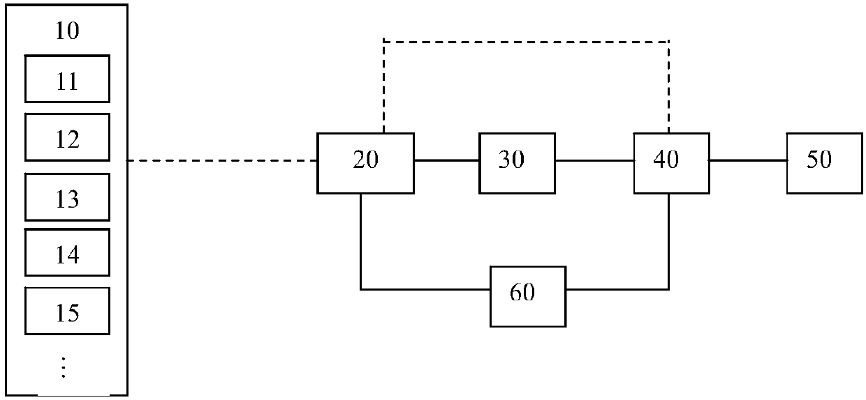
[0044] Such as figure 1 Shown is a schematic diagram of logic modules of the communication device of the present invention.

[0045] The present invention provides a kind of early warning system based on stroboscopic information, such as figure 1 shown. The early warning system based on stroboscopic information of the present invention includes a sensing unit 10 , at least one optical transceiver unit 20 and a control unit 40 . The sensing unit 10 includes several sensors and at least one light modulation module 11 . The sensors and at least one light modulation module 11 can be arranged in many ways, and the user can set them according to requirements. For example, in the sensing unit 10 , each sensor is individually connected to a light modulation module 11 . Alternatively, multiple sensors are connected to the same light modulation module 11 .

[0046] The light modulation module 11 is used to modulate the electrical signal transmitted by the sensor into a required lig...

Embodiment 2

[0070] This embodiment is a further improvement on Embodiment 1, and repeated content will not be repeated here.

[0071] This embodiment provides an early warning system based on stroboscopic information. Such as figure 1 As shown, the early warning system based on stroboscopic information of the present invention not only includes a sensing unit 10, at least one optical transceiver unit 20 and a control unit 40, but also includes an analysis unit 30 between the optical transceiver unit 20 and the control unit 40 . The analysis unit 30 is used for calculating and analyzing the data. The analysis unit can be one or more of computers, central processing units, microprocessors, ASICs, single-chip microcomputers, servers, and cloud servers.

[0072] The evaluation unit 30 evaluates the security situation, ie the security information, based on at least one monitoring item in the light signal. The safety information includes at least one or more of the safety environment, safet...

Embodiment 3

[0086] This embodiment is a further improvement on Embodiment 1 and Embodiment 2 and their combination, and the repeated content will not be repeated.

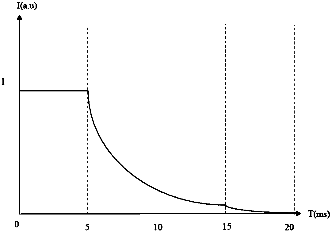
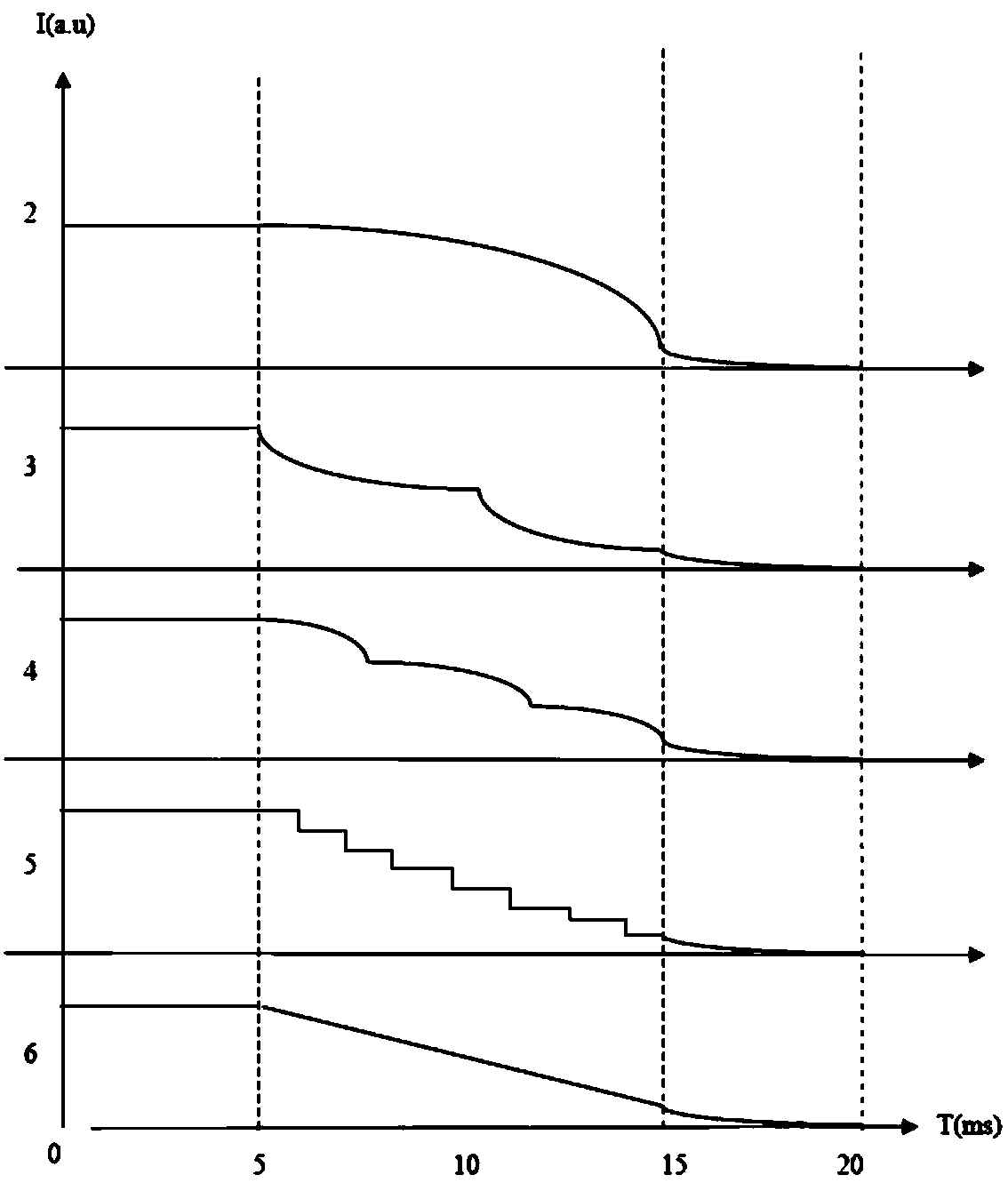
[0087] This example is for Figure 2 to Figure 10 The characteristic curve change of the optical signal is described in detail. The variation trend of the characteristic curve of the preferred first light-emitting stage of the present invention is as follows Figure 2 to Figure 4 shown. The horizontal axis in the figure represents time, and the unit is ms. The vertical axis represents intensity or relative intensity, and the unit is not limited, expressed by the international general symbol a.u. The light-emitting period of this embodiment is preferably 20ms, the first light-emitting period is 0-5ms, the second light-emitting period is 5-15ms, and the third light-emitting period is 15-20ms.

[0088] Such as figure 2 and image 3 In the luminescence curves No. 1-6 shown, the luminous intensity in the first luminescent st...


PUM


Abstract

The invention relates to an early-warning system based on stroboscopic information. The system comprises a sensing unit, an optical transmit-receive unit and a control unit. The sensing unit comprisesan optical modulation module and sensors. The optical modulation module is used for modulating an electrical signal carrying monitoring information sent by the sensor into an optical signal comprising at least two light-emitting phases in a light-emitting period, wherein at least one monitoring information is set in a manner of modulating luminescence time length, characteristic curve and/ or spectral change rules of light in at least one light-emitting phase, and at least one monitoring information, light intensity/brightness of which is approaching to zero candela change, is set in a mannerof modulating luminescence time length, characteristic curve and/ or spectral change rules of light in at least one light-emitting phase; and when at least one monitoring information in the optical signal received by the at least one optical transmit-receive unit is in an early-warning state, the control unit sends an early-warning instruction to the at least one optical transmit-receive unit andcontrols the at least one optical transmit-receive unit to project a guide light pattern corresponding to the safety level to indicate a safe route.

Description

technical field [0001] The invention relates to the technical field of information early warning, in particular to an early warning system based on stroboscopic information. Background technique [0002] In the safety monitoring system, the most basic and most important function is to monitor the dynamic changes of the analog data at the monitoring point in real time, to give an alarm when the preset alarm value is reached, and to report to the security when the preset alarm value is reached or exceeded. The monitoring system sends out a control signal, so that the security monitoring system sends out an alarm sound, and an alarm window pops up at the terminal of the security monitoring system for alarming. [0003] For example, in a factory production environment, dedicated wiring is required for early warning systems. When the sensor detects that a certain monitoring value exceeds the standard and prepares for an early warning, the line between the sensor and the controll...

Claims


Application Information

Patent Timeline
IPC IPC(8): G05B19/042
Inventor 李成宇张洪杰王森
Owner ZHONGKE RARE EARTH (CHANGCHUN) CO LTD
Why Eureka
Try Eureka