Induction coil for a hearing aid

Inactive Publication Date: 2005-06-30
SIEMENS AUDIOLOGISCHE TECHN
View PDF4 Cites 7 Cited by
  • Summary
  • Abstract
  • Description
  • Claims
  • Application Information

AI Technical Summary

Benefits of technology

[0005] To avoid said coupling effects, the induction coil is as a rule located in the hearing aid as far away as possible from the receiver. As said coil's length often precludes achieving an adequate distance between itself and the receiver, in such cases a mu-metal sheet is inserted between said receiver and said coil. The mu-metal sheet indeed reduces the coupling effects, but it also lowers the induction coil's sensitivity.

Problems solved by technology

The mu-metal sheet indeed reduces the coupling effects, but it also lowers the induction coil's sensitivity.

Method used


Image

  • Induction coil for a hearing aid
  • Induction coil for a hearing aid
  • Induction coil for a hearing aid

Examples


Embodiment Construction

[0024] The exemplary embodiment described in more detail below is a preferred embodiment of the present invention.

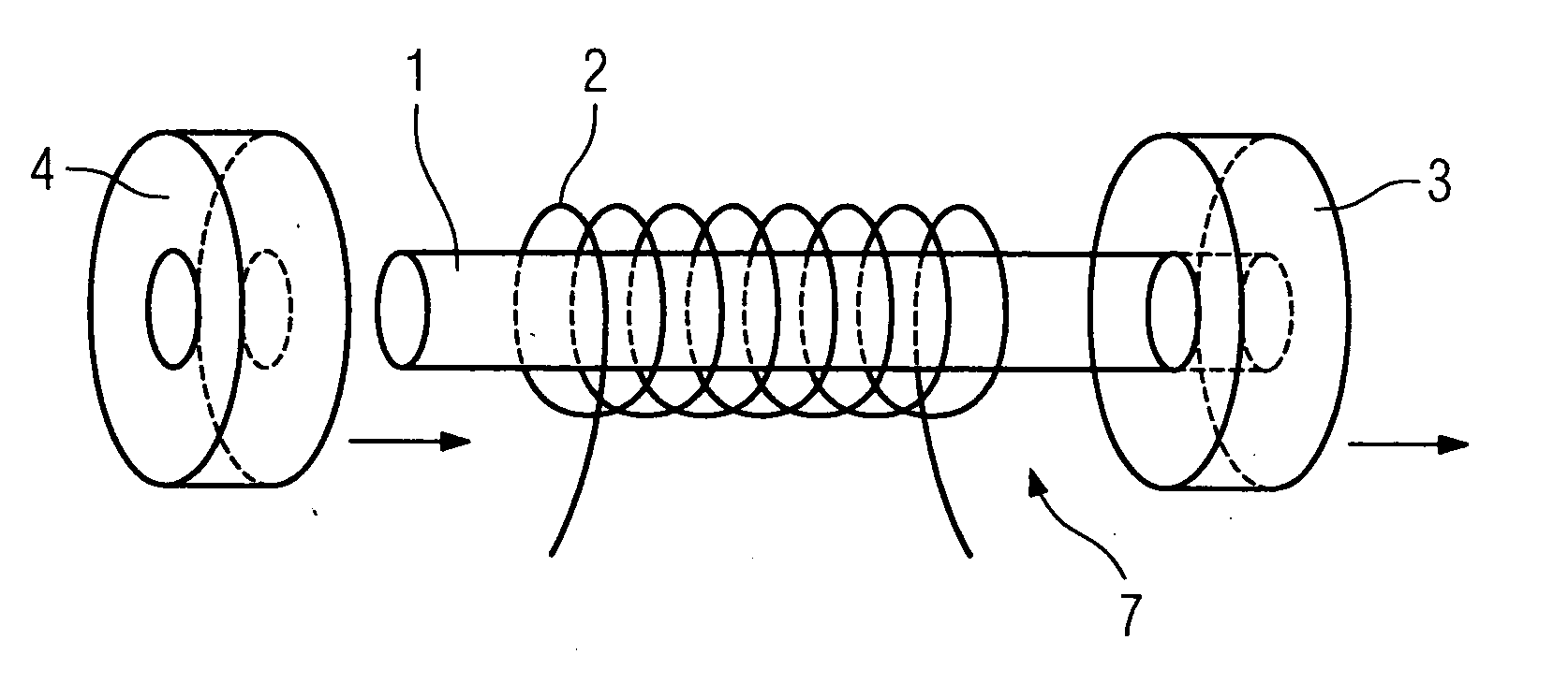
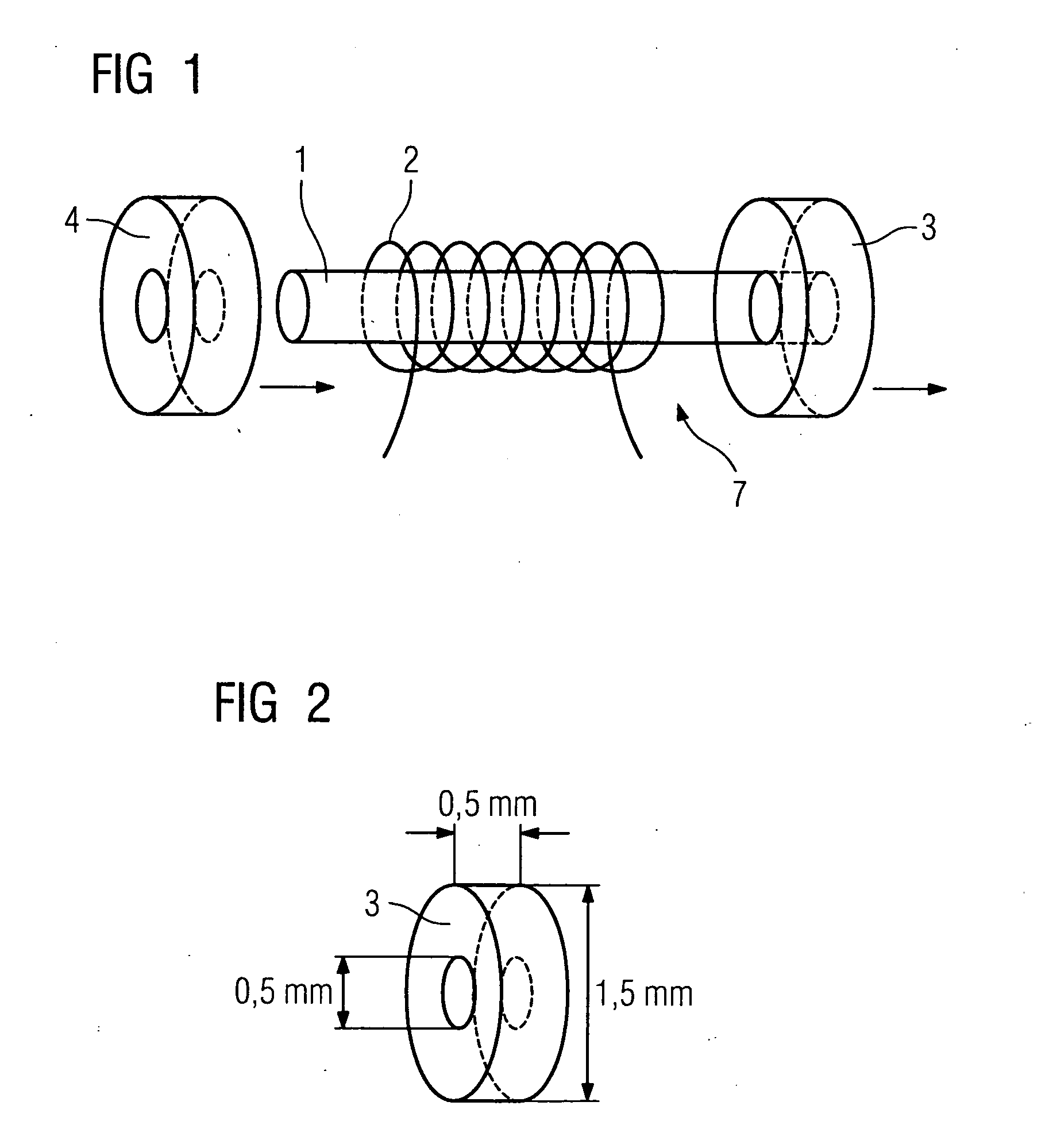
[0025] An induction coil according to the invention consists of a core 1 onto which is wound a winding 2. Attached to both ends of the core 1 are mu-metal disks or, as the case may be, mu-metal rings 3 and 4. Said mu-metal rings 3 and 4 are mounted by being pasted or, as the case may be, pressed onto the cylindrical core 1, as is indicated in FIG. 1 by the arrows.

[0026] A mu-metal ring 3 typically has the dimensions shown in FIG. 2. It accordingly has an outside diameter of approximately 1.5 mm and a thickness of approximately 0.5 mm. In the example chosen it further has a drilled hole having an inside diameter of 0.5 mm.

[0027] Corresponding mu-metal disks can also be pasted onto the end faces of the core as an alternative to the mu-metal rings 3 and 4 shown in FIGS. 1 and 2.

[0028] Both the mu-metal disks and the mu-metal rings 3 and 4 cause the core or, as the case ...


PUM


Abstract

The aim is to reduce the costs of producing hearing aids whose induction coils are dumbbell shaped. To achieve this it is proposed mounting the core extensions (3) onto the ends of the core (1). Mu-metal disks or, as the case may be, mu-metal disks rings (3, 4) are preferably attached to the ends of the core (1). This will ensure production at an economical price; the induction coil will furthermore have high magnetic lateral sensitivity, which is advantageous during telephoning.

Description

CROSS REFERENCE TO RELATED APPLICATIONS [0001] This application claims priority to the German application No. 10356094.7, filed Dec. 1, 2003 and which is incorporated by reference herein in its entirety. FIELD OF INVENTION [0002] The present invention relates to an induction coil or, as the case may be, a telephone coil for a hearing aid, which coil has a cylindrical core and at least one core extension enlarging said core in a radial direction at one of its ends. The present invention further relates to a corresponding method for producing an induction coil of said type for hearing aids. BACKGROUND OF INVENTION [0003] Induction coils are employed in hearing aids for the purpose of receiving magnetic signals. Typical areas of application in which the properties of induction coils can be exploited include, alongside telephony, catering for the hard of hearing in schools, cinemas, churches, and the like. [0004] The induction coils currently used in hearing aids are typically 9 mm long...

Claims


Application Information

Patent Timeline
IPC IPC(8): H01F17/04H01F41/02H04R25/00
CPCH01F17/045H04R2225/51H04R25/554H01F41/0206
Inventor KASZTELAN, THOMAS
Owner SIEMENS AUDIOLOGISCHE TECHN
Why Eureka
Try Eureka