Method and apparatus for defeating effects of color burst modifications to a video signal

a video signal and color burst technology, applied in the field of video signal processing methods and apparatuses, can solve the problems of color fidelity, preprogrammed memory, and the number of video lines per field, and achieve the effect of attenuating or eliminating the effect of the color stripe process, attenuating or eliminating the effect of the color stripe burs

Inactive Publication Date: 2005-06-30
ROVI SOLUTIONS CORP
View PDF15 Cites 11 Cited by
  • Summary
  • Abstract
  • Description
  • Claims
  • Application Information

AI Technical Summary

Benefits of technology

[0016] A modification circuit which also receives the video signal, and uses the information as to the location of the color stripe bursts, removes and/or modifies the color stripe bursts or otherwise modifies the video signal (i.e. modifies the horizontal sync pulse immediately preceding the color stripe burst) so that the effect of the color stripe process is attenuated or eliminated.
[0017] With regard to the present invention, it has been found that it is not necessary to completely eliminate the color stripe bursts; with typical commercially available television sets and VCRs, eliminating some of the color stripe bursts or attenuating the color stripe bursts either in terms of amplitude or duration, or removing or attenuating a portion of each or most colorstripe bursts, has been found effective to overcome the effect of the color stripe process, allowing a recordable (copiable) video signal to be produced.
[0018] Sometime

Problems solved by technology

However, the resultant color picture from a subsequent video tape recording shows variations in the color fidelity that appear as bands or stripes of color error.
Commercial embodiments of the teachings of this patent typically limit the number of video lines per field having the induced color error or color stripes.
Other times, even where it is so fixed, it is not desired or possibl

Method used


Image

  • Method and apparatus for defeating effects of color burst modifications to a video signal
  • Method and apparatus for defeating effects of color burst modifications to a video signal
  • Method and apparatus for defeating effects of color burst modifications to a video signal

Examples


Embodiment Construction

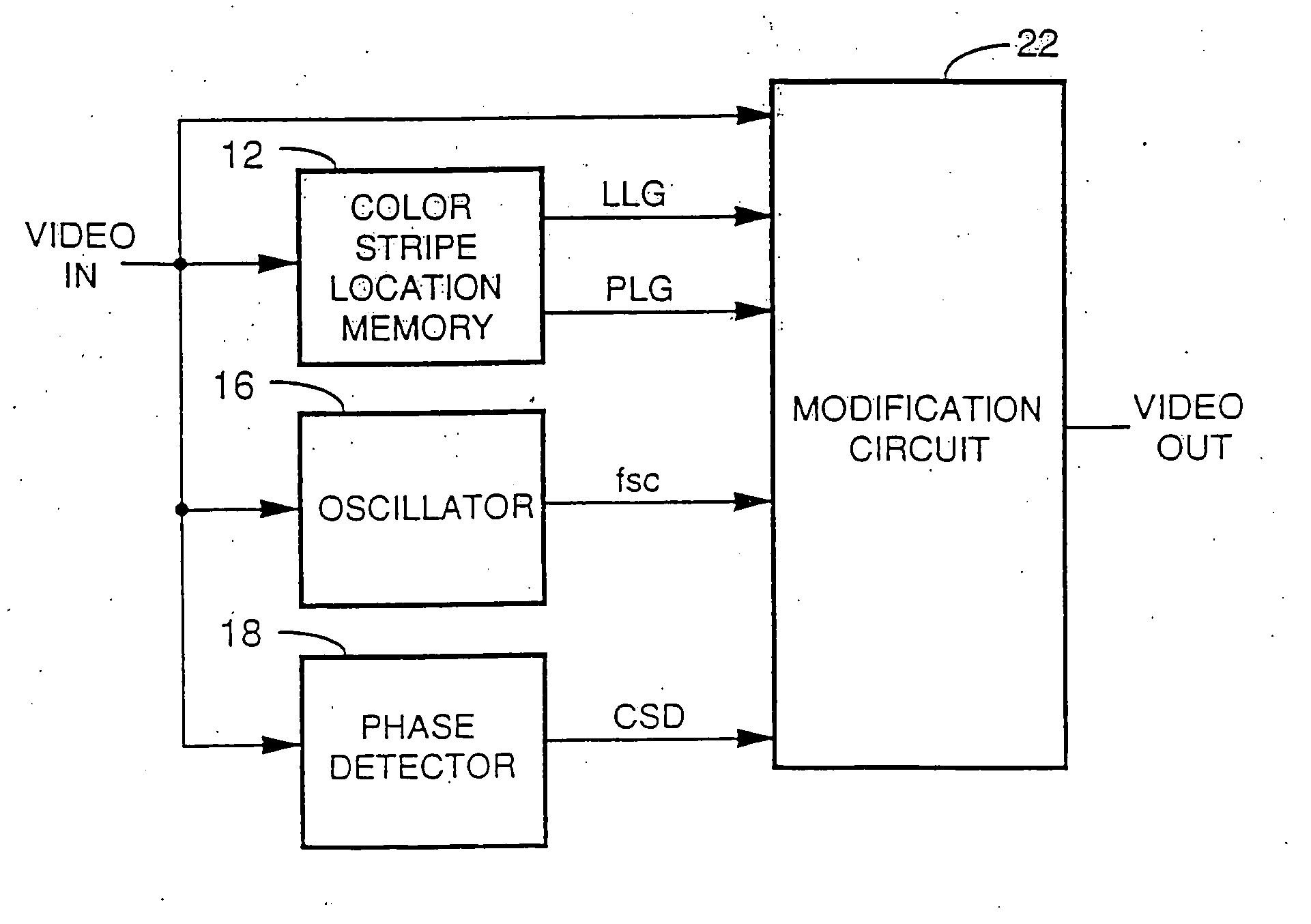
[0047] The following describes a number of embodiments to defeat the color stripe process. First is a description relating to waveforms and processes; second is a description of various related circuits.

Process Description

[0048] The following are various color stripe defeat processes in accordance with the invention.

[0049] 1. One or more color burst phase lock loops (or other circuits) are used to find the mean color burst phase and then all color bursts (whether color stripe or not) are replaced throughout the video signal.

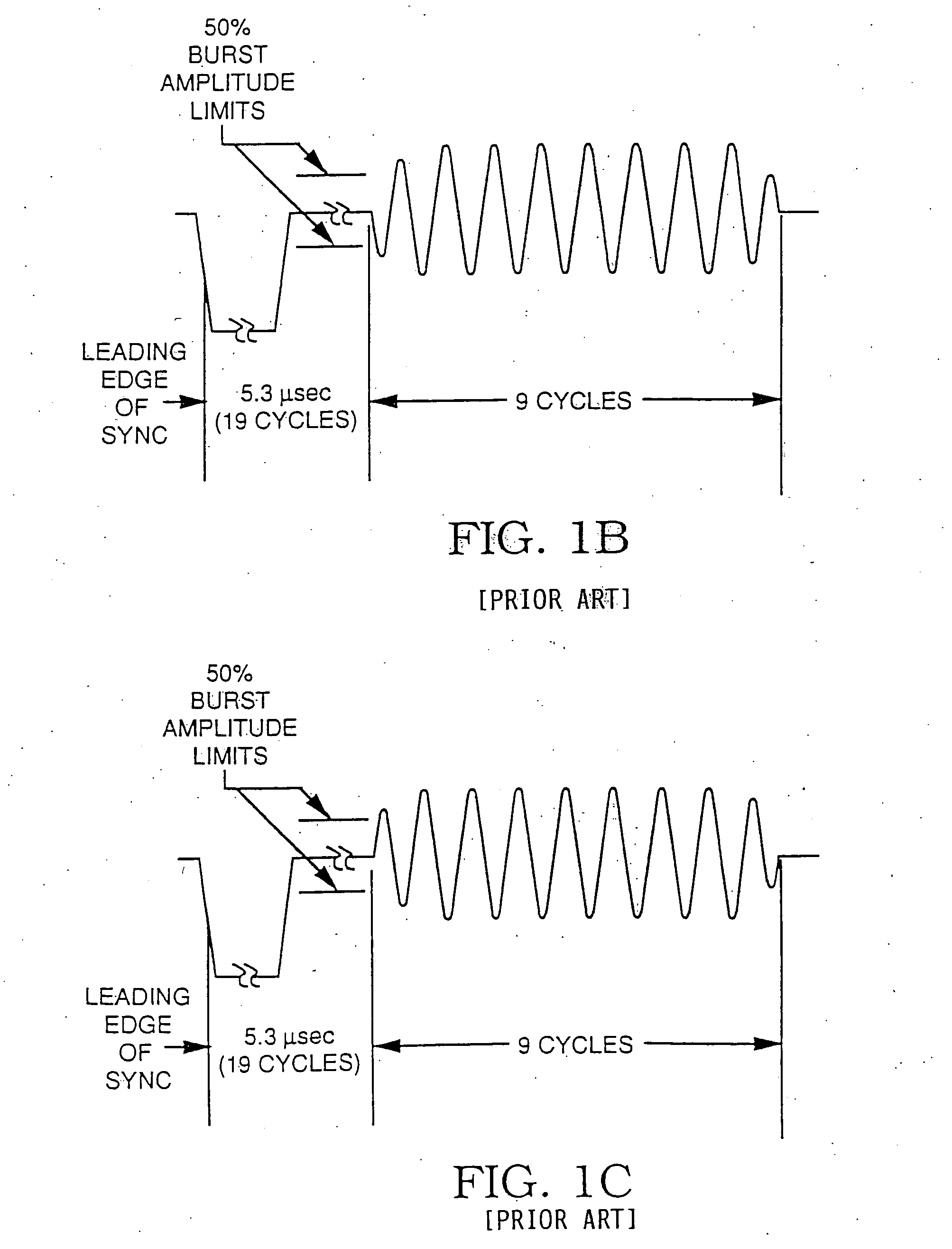
[0050] This replacement may be of only a portion of a particular color burst. For instance, of the standard eight to ten cycles of NTSC color burst, one may replace e.g. the first five cycles, the last five cycles, or any other group of e.g. four to six cycles. The replaced cycles need not be consecutive; one may replace alternate cycles, leaving “good” (corrected) cycles interspersed with “bad”. (color stripe) cycles. It also is possible to add corrected co...


PUM


Abstract

A copy protection color stripe process is defeated first by determining the location of the video lines including the color stripe process. Then some or all of the lines including the modified color bursts are modified so as to render the overall video signal recordable. The modification is accomplished in a number of ways, including phase shifting the color stripe burst into the correct phase, replacing, attenuating and or eliminating some of the color stripe bursts or at least a portion of particular color burst envelopes so that they are no longer effective, mixing the color stripe burst with color stripe signals of the correct phase so as to eliminate most or all of the phase error present or modifying the horizontal sync pulse signals immediately preceding the modified color bursts so that the modified color bursts are not detected by a VCR and hence have no effect.

Description

BACKGROUND OF THE INVENTION [0001] 1. Field of the Invention [0002] The present invention pertains to a method and apparatus for processing a video signal, and more particularly to removing (defeating) effects of phase modulation of the color burst component of the video signal. [0003] 2. Description of the Prior Art [0004] U.S. Pat. No. 4,577,216, “Method and Apparatus For Processing a Video Signal,” John O. Ryan, issued Mar. 18, 1986 and incorporated by reference, discloses modifying a color video signal to inhibit the making of acceptable video recordings thereof. A conventional television receiver produces a normal color picture from the modified signal. However, the resultant color picture from a subsequent video tape recording shows variations in the color fidelity that appear as bands or stripes of color error. Colloquially the modifications are called the “color stripe system” or the “color stripe process”. Commercial embodiments of the teachings of this patent typically lim...

Claims


Application Information

Patent Timeline
IPC IPC(8): H04N5/913H04N9/455
CPCH04N5/913H04N2005/91371H04N9/455
Inventor QUAN, RONALD
Owner ROVI SOLUTIONS CORP
Why Eureka
Try Eureka