
Massage glove

Inactive Publication Date: 2005-06-30
GELBER MITCHELL L +1
View PDF26 Cites 35 Cited by
  • Summary
  • Abstract
  • Description
  • Claims
  • Application Information

AI Technical Summary

Benefits of technology

[0004] In accordance with this invention there is provided a massage glove in which small vibratory elements or motors are affixed within the glove on the palm side thereof rather than the back-of-hand side of the glove. The vibratory motors are sufficiently small and lightweight that they do not interfere with the movement of the user's fingers and hand in traditional massaging force applications and movement.
[0007] The vibratory motors used in the glove of the invention preferably have a height less than about 0.15 inches. Between the motors and the flexible material that forms the exterior of the glove padding can be provided so as to avoid harsh engagement between the glove and the massage recipient where the motors are located. Harmful or unpleasant engagement with the massage recipient is thus avoided.

Problems solved by technology

A disadvantage to these is that they are placed on the back of the hand or on the backs of the fingers (rather than the palm side) and vibration must be transmitted through the hand or fingers.
The hand and fingers are subject to going numb as a result.

Method used


Image

  • Massage glove
  • Massage glove
  • Massage glove

Examples


Embodiment Construction

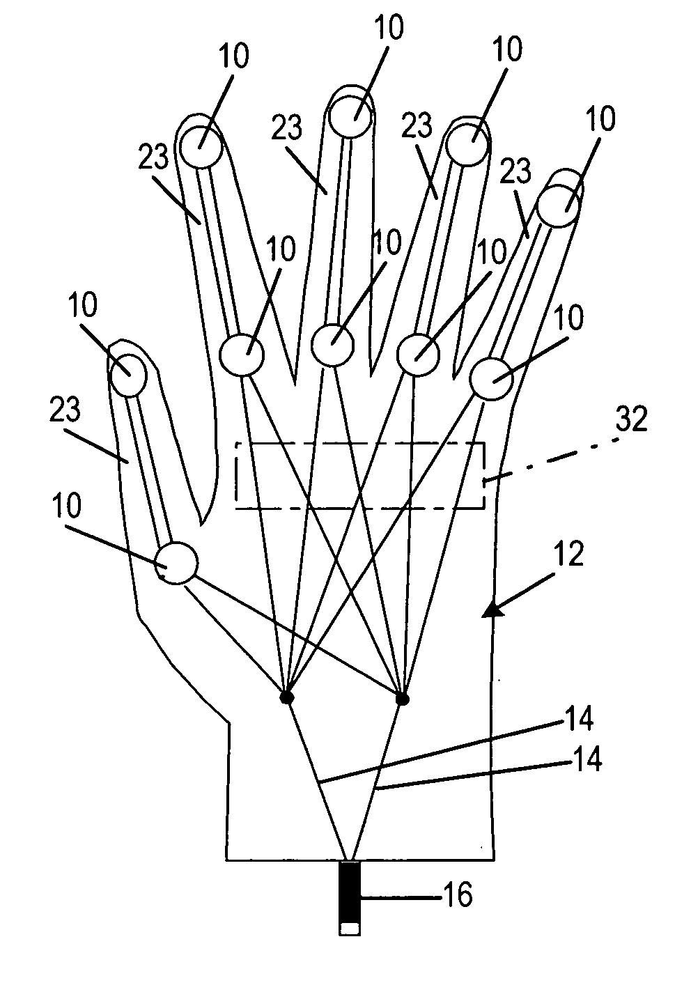
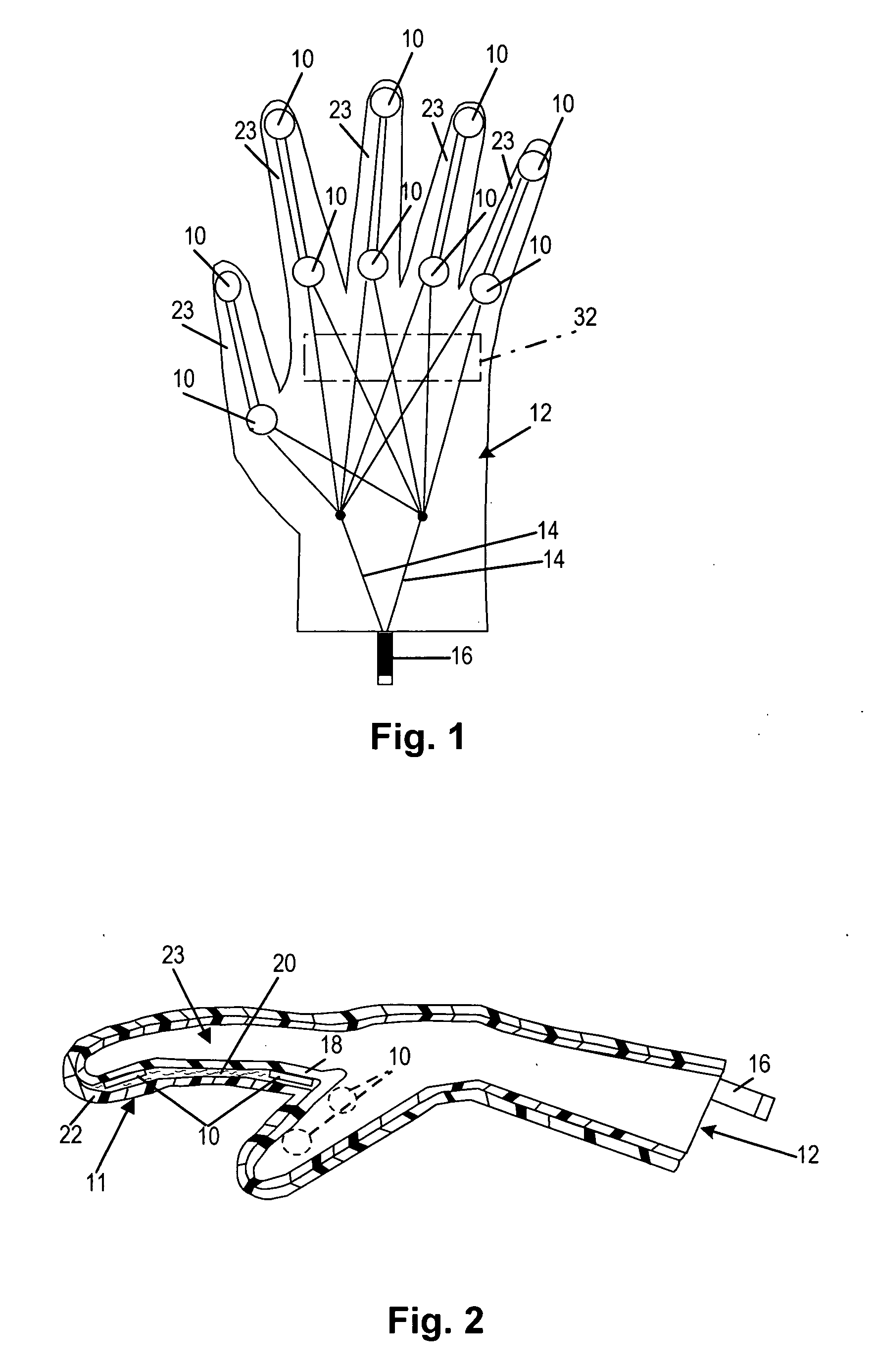
[0015] As shown diagrammatically in FIG. 1, relatively small disc-like vibrating motors 10 that attach to the palm side 11 of a glove 12 at selected locations in accordance with this invention permit vibrations from well distributed locations on the hands to be applied during therapeutic massage while causing little or no interference with normal massaging movement of the therapists' hands and fingers. Each vibratory element is an individual vibratory motor from which runs electrical leads 14 to a light-weight battery operated electrical power source 16.

[0016] The glove 12 is preferably fashioned of a flexible material of preferably pleasant tactile qualities. As illustrated in FIG. 2, the glove 12 may be a multi-layer glove having an inner liner 18, a light layer of padding 20 isolating the vibratory elements 10 from the patient somewhat, and an outer glove shell 22 of the tactically pleasant thermoplastic or rubber-like preferably hypoallergenic material. In the preferred embodim...


PUM


Abstract

A massage glove having a plurality of vibratory motors secured within it on the palm side. The glove employs small vibrator motors located within the glove fingers. The motors are of a size and weight such that ordinary movement of the therapist's fingers within the glove in traditional massaging movements is not hampered. A heating element may be included in the glove for applying heat in addition to the vibration and the more traditional massage.

Description

FIELD OF THE INVENTION [0001] A massage glove in accordance with the present invention is provided for the relief of stress-related muscle tension and for other therapeutic massage. BACKGROUND [0002] Bulky vibrators that attach to the back of the hand have been known for a long time for vibrating the hand in order to accomplish a vibratory massage. There have also been suggestions in the art of vibrators attached to the backs of the fingers for this purpose. These known units have often employed eccentric-type vibrators whereby a motor drives an off balance armature or rotor. A disadvantage to these is that they are placed on the back of the hand or on the backs of the fingers (rather than the palm side) and vibration must be transmitted through the hand or fingers. The hand and fingers are subject to going numb as a result. In one instance, a glove has been suggested with vibratory elements at the fingertips driven by apparently mechanical connectors running back along the glove to...

Claims


Application Information

Patent Timeline
IPC IPC(8): A61H1/00A61H7/00A61H23/02A61H37/00
CPCA61H7/005A61H23/02A61H2205/065A61H2201/0228A61H2201/0207
Inventor GELBER, MITCHELL L.WISE, WILLIAM R.
Owner GELBER MITCHELL L
Learn More