Juncture for a high pressure fuel system

Active Publication Date: 2005-06-30
CUMMINS INC
View PDF17 Cites 20 Cited by
  • Summary
  • Abstract
  • Description
  • Claims
  • Application Information

AI Technical Summary

Benefits of technology

[0010] In view of the foregoing, one aspect of the present invention is a mechani

Problems solved by technology

A limitation of such high pressure fuel injection systems briefly described above has been found in that the high pressures of the pressurized fuel, which in certain instances, reach up to 30,000 p.s.i. or higher, for example, can cause fatigue failure in the various components of the fuel injection system.
In particular, the rapid stress cycling of the high pressure pump and/or the common rail at these high pressures can cause the fuel passages in the fuel injection system to fail due to fatigue.
Such fatigue failure has been found

Method used


Image

  • Juncture for a high pressure fuel system
  • Juncture for a high pressure fuel system
  • Juncture for a high pressure fuel system

Examples


Embodiment Construction

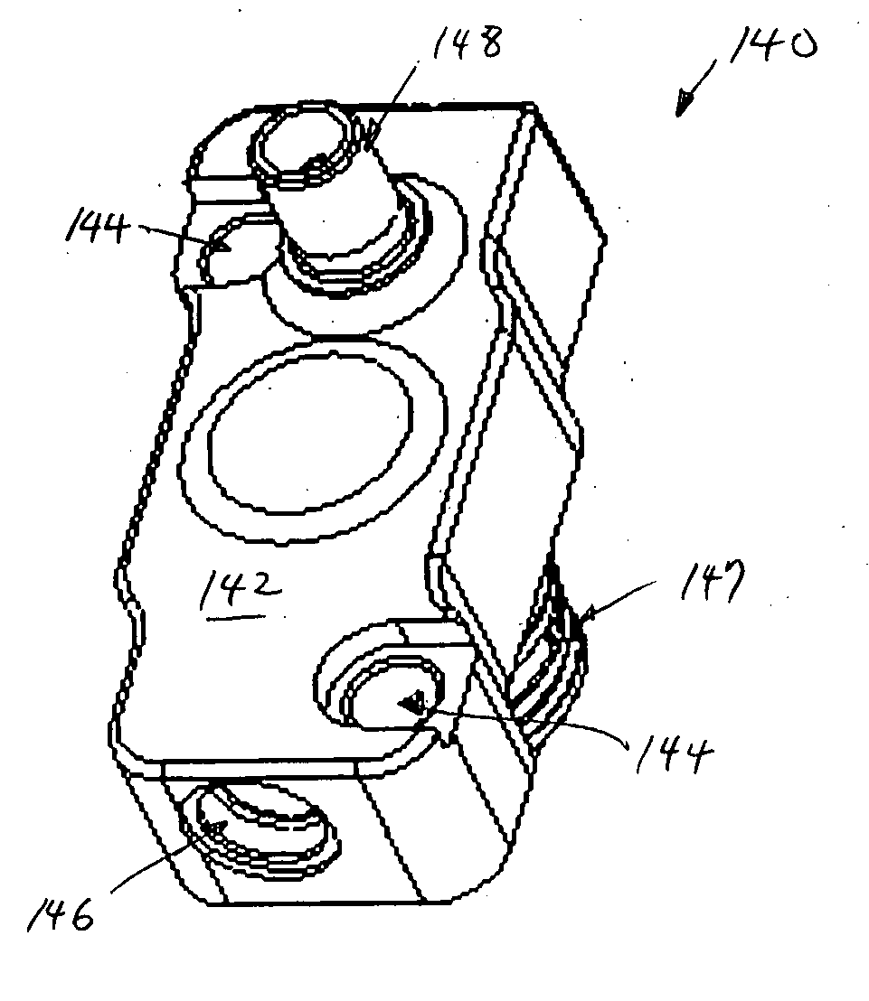
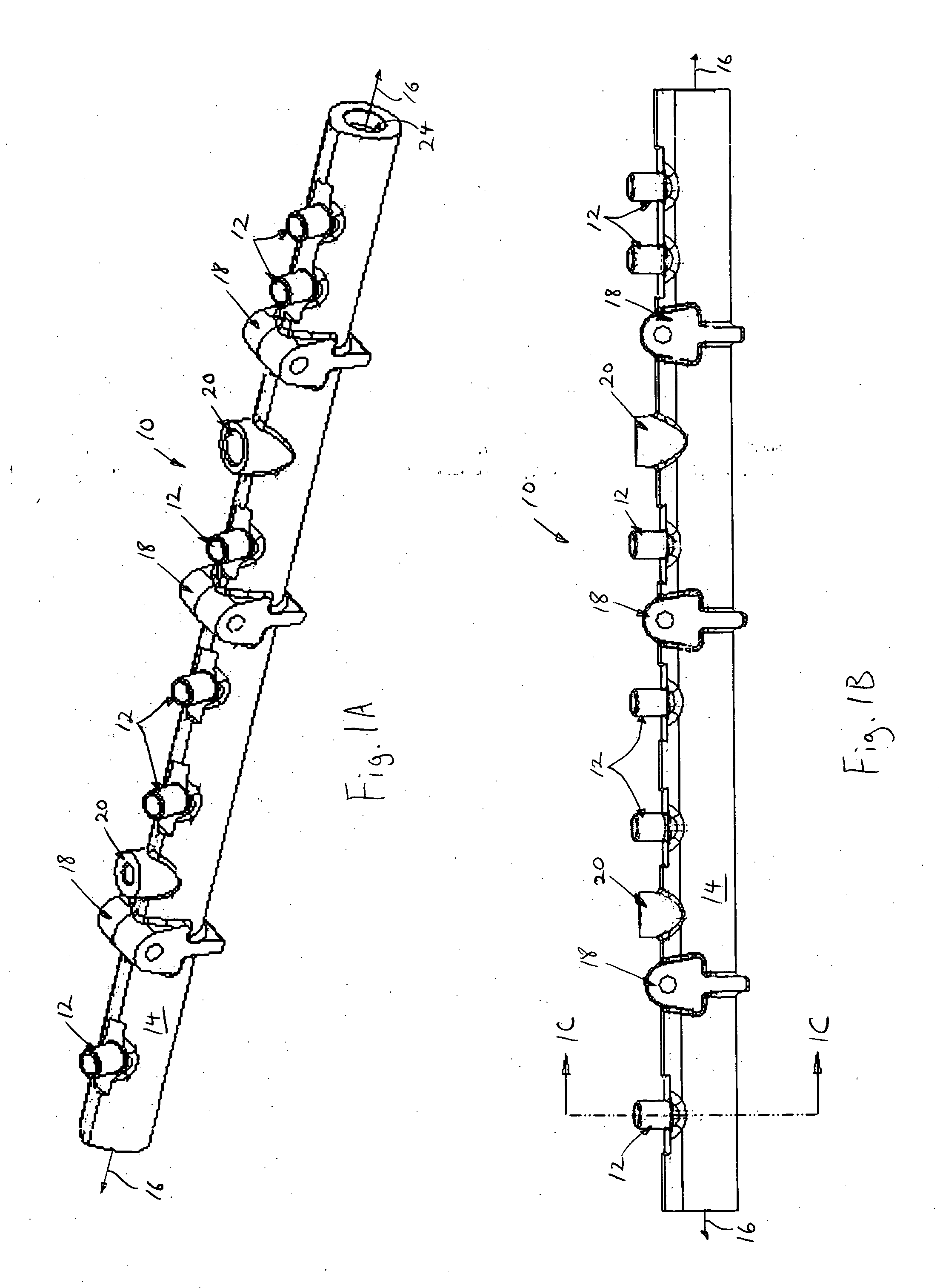
[0039]FIGS. 1A and 1B show perspective and profile views of a common rail 10 used in a high pressure fuel system of an internal combustion engine (not shown), the common rail 10 including a plurality of connectors 12 that have junctures in accordance with one embodiment of the present invention. The common rail 10 is adapted to receive pressurized fuel from a fuel pump (not shown) of the high pressure fuel system, and to distribute the pressurized fuel to a plurality of fuel injectors (not shown) that are fluidically connected to the junctures of connectors 12.

[0040] As described in detail below, the junctures in accordance with the present invention reduces the stresses caused by the rapid pressure cycling that occurs within the common rail 10 by the pressurized fuel, thereby reducing the likelihood of fatigue failure of the juncture. It should be noted that as used herein, the term “juncture” generally refers to the intersection of two or more passages in fluidic communication to...


PUM


Abstract

A juncture and method for changing direction of fuel flow in a high pressure fuel injection system such as a common rail and/or a fuel pump, the juncture comprising a body, a first passage formed in the body having a first diameter and a longitudinal axis extending therethrough, the first passage including a groove positioned along a portion of the longitudinal axis, and a second passage formed in the body having a second diameter, a central axis extending therethrough, and an opening, the opening of the second passage being provided in the groove of the first passage to allow fluidic communication between the second passage and the first passage so that stresses at the juncture caused by high pressure fuel changing direction of flow is reduced.

Description

BACKGROUND OF THE INVENTION [0001] 1. Field of the Invention [0002] The present invention is directed to a mechanism and method for reducing likelihood of fatigue failure in a high pressure fuel system. In particular, the present invention is directed to a specific juncture geometry that may be utilized in high pressure pump and / or common fuel rail systems. [0003] 2. Description of Related Art [0004] With the advent of increased fuel economy and reduced emissions requirements imposed by the government, various fuel systems have been developed to precisely control the amount of fuel that is injected during the injection events of a combustion cycle. In particular, high pressure fuel injection systems have been developed which provide increased control of the fuel injected by the fuel injectors of an internal combustion engine in comparison to conventional fuel injection systems. [0005] Such high pressure fuel injection systems typically utilize at least one high pressure pump that pr...

Claims


Application Information

Patent Timeline
IPC IPC(8): F02M37/04F02M55/02F02M59/48G06F17/24
CPCF02M55/025F02M2200/80F02M59/48F02M37/04F02M55/02
Inventor DENTON, JAMES E.SHAULL, ANTHONY A.SIMMONS, SCOTT R.STATE, MATTHEW B.WIELAND, TODD M.
Owner CUMMINS INC
Why Eureka
Try Eureka