In-vehicle display apparatus

a technology for vehicle interiors and display devices, applied in the field of vehicle display devices, can solve the problems of poor appearance of the vehicle display devices and marring the beauty of the vehicle interior

Inactive Publication Date: 2005-07-07
FUJITSU GENERAL LTD
View PDF8 Cites 23 Cited by
  • Summary
  • Abstract
  • Description
  • Claims
  • Application Information

AI Technical Summary

Benefits of technology

[0006] It is an object of the present invention to solve at least the above problems in the conventional technology.

Problems solved by technology

However, when the clearance is excessive, there occurs a problem that the appearance of the in-vehicle display apparatus becomes poor, which results in marring the beauty of a vehicle interior.

Method used


Image

  • In-vehicle display apparatus
  • In-vehicle display apparatus
  • In-vehicle display apparatus

Examples


first embodiment

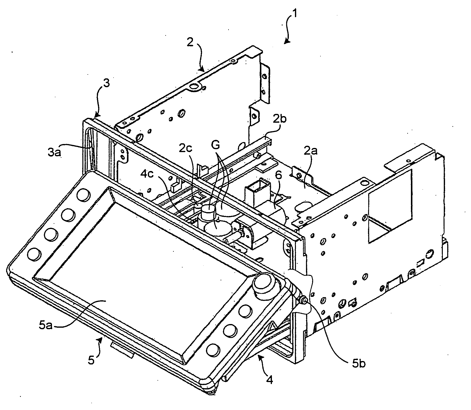
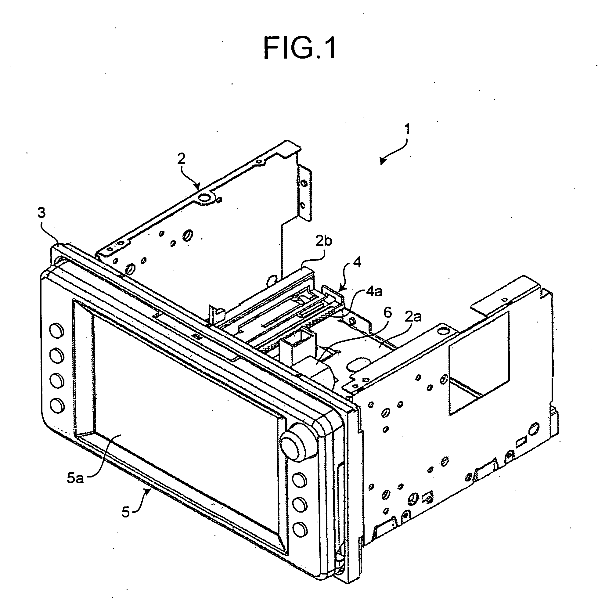
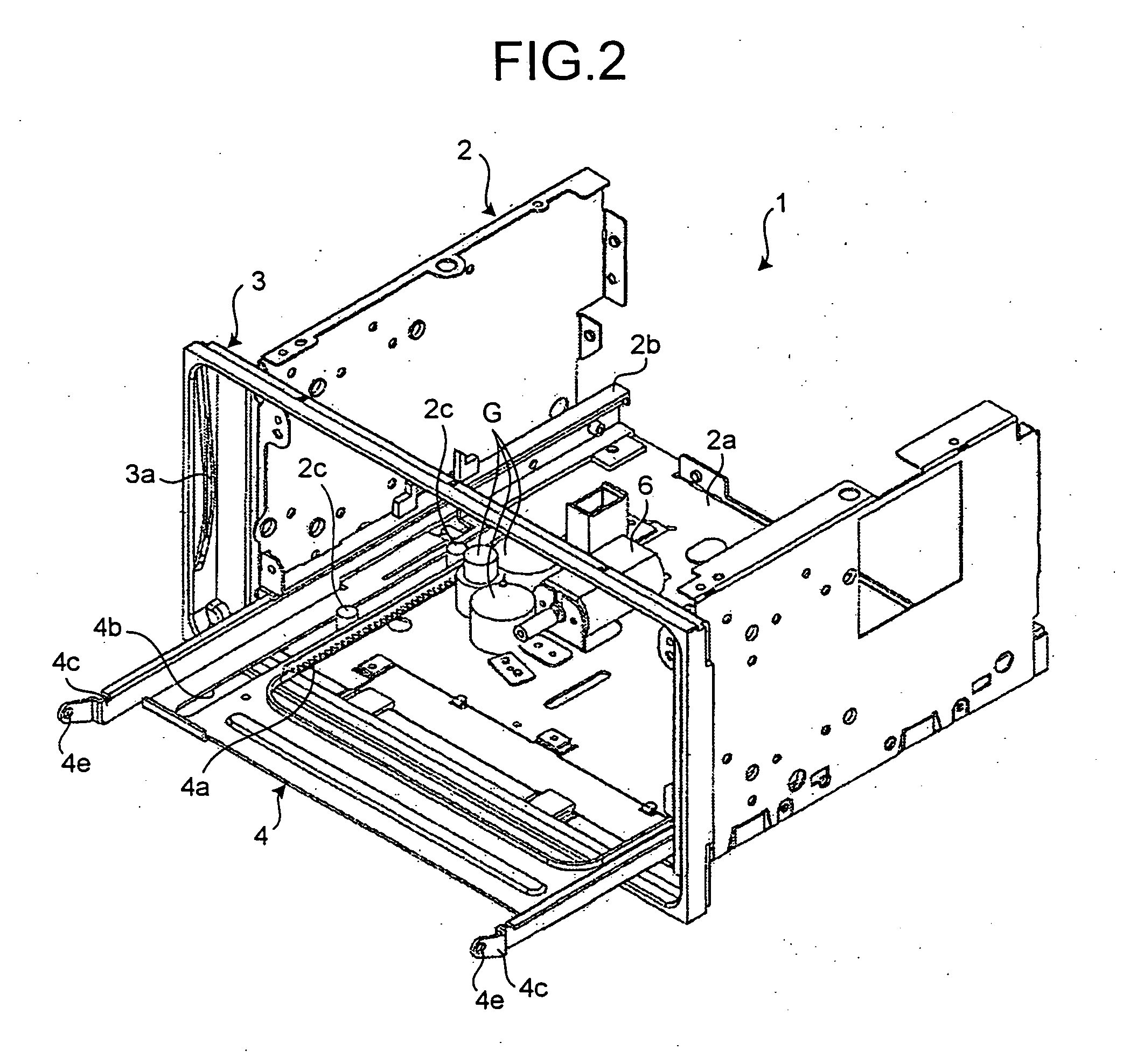
[0028]FIG. 1 is a perspective view of an in-vehicle display apparatus (hereinafter, “a display apparatus”) 1 according to the present invention. FIG. 2 is a perspective view of the display apparatus 1 shown in FIG. 1, from which a display panel has been removed. FIG. 3 is a perspective view of a state where a display panel has been inclined in the display apparatus 1 shown in FIG. 1. The display apparatus 1 includes a main unit 2 and a display panel 5.

[0029] The main unit 2 is a casing where a unit in which various electronic devices, which reproduce a recording medium such as CD, MD, and DVD, are used is disposed. As shown in FIGS. 1 to 3, the main unit 2 is attached with a framed front panel 3 serving as an accommodating unit at a front portion thereof and is provided on a bottom plate 2a with a slider 4 such that the slider 4 can be drawn out in a horizontal direction.

[0030] The front panel 3 is molded from synthetic resin in a frame shape, and is formed at both sides thereof wi...

second embodiment

[0043]FIG. 8 is a sectional plan view of a principal portion of the display apparatus 10 according to the FIG. 9 is a front view of the display apparatus 10 shown in FIG. 8. FIG. 10 is a vertical sectional view of the display apparatus 10 shown in FIG. 8. The display apparatus 10 includes the main unit 2 and the display panel 5, and it is mounted on an instrument panel 14 via a framed member 12 with a mounting opening 12a, called “a cluster”, which has been mounted on the vehicle mount member such as a dashboard or the instrument panel 14 in advance. As shown in FIGS. 8 and 9, the display panel 5 is formed on a lower face with a guide groove 5e, while the cluster 12 is provided at a position thereof corresponding to the guide groove 5e with a positioning rib 12b engaged with the guide groove 5e. Accordingly, the display panel 5 is positioned to the cluster 12 in a horizontal direction.

[0044] As shown in FIG. 8, the display panel 5 is pin-connected, at its both lower sides, to coupl...

sixth embodiment

[0062] An inclined angle of the display panel 5 during translation thereof can be adjusted by the contacting position of the lower end edge of the inclining lever 50 and the distal end edge of the slider 4. Accordingly, as described later, since the sixth embodiment employs a constitution that a lower portion of the display panel 5 is inclined by a predetermined angle (0.5°), stepping occurring during accommodating operation of the display panel 5 can be minimized.

[0063] The main unit 2 is provided with the pressing lever 40 that presses the bearing 5b fixed at an upper end of the display panel 5 forward (leftward in FIG. 16) by a spring force of a pressing spring 41. The bearing 5b can be moved within the guide groove 3a by the pressing lever 40 rotated about a pivoting shaft 42 by a spring force of the pressing spring 41.

[0064] The guide groove 3a includes a horizontal groove Th that extend in a horizontal direction and is formed to be wider than a vertical groove Tv formed to ex...


PUM


Abstract

A main unit includes a slider and a guide groove. A display panel includes a slider engaging portion coupled to the slider being guided by the slider and a guide-groove engaging portion slidably engaged with the guide groove being guided by the guide-groove so that the display panel can be inclined. A pressing lever presses the guide-groove engaging portion with resilient force of a resilient member. The guide-groove includes a parallel groove formed in parallel with a direction of movement of the slider; and a curved groove having a width narrower than that of the parallel groove and being connected to the parallel groove. The guide-groove engaging portion moves in the parallel groove by the movement of the slider and a pressing force of the pressing lever.

Description

BACKGROUND OF THE INVENTION [0001] 1.) Field of the Invention [0002] The present invention relates to a display apparatus to be mounted as in-vehicle equipment, and in particular to an in-vehicle display apparatus that can provide an excellent appearance by a proper positioning. [0003] 2.) Description of the Related Art [0004] In a vehicle such as an automobile, various electronic devices for reproducing a recording medium such as compact disk (CD), magnetic disk (MD), or digital versatile disk (DVD) is mounted on a mount member such as a dashboard or an instrument panel, and an in-vehicle display apparatus provided with a display panel such as a liquid crystal panel is used in each of the electronic devices (see, for example, Japanese Patent Application Laid-open Publication No. H5-42853). For example, the in-vehicle display apparatus is assembled so as to be capable of being inclined to a user's side by drawing a lower portion of a display panel out of a main unit of the display a...

Claims


Application Information

Patent Timeline
Patent Type & Authority Applications(United States)
IPC IPC(8): B60K35/00B60R11/02G09F11/00G12B9/08
CPCB60K35/00Y10T16/5443Y10T16/545B60K2350/405B60K2370/67B60K2370/1533
Inventor SHIMIZU, YUKIOYURI, SHINSUKE
Owner FUJITSU GENERAL LTD
Why Eureka
Try Eureka